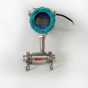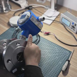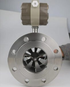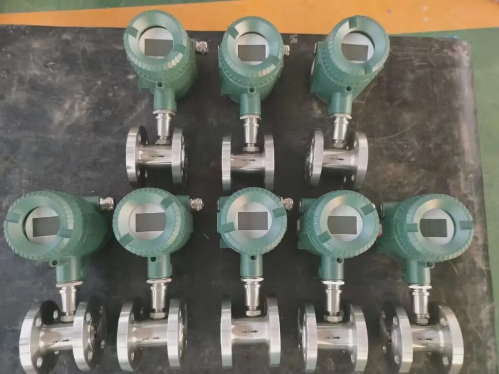

In EPC projects, the flow meter is not just an instrument — it is the data source that determines whether process control, billing, and safety systems do their job correctly.
The Critical Role of Flow Measurement in EPC Projects
Every EPC project has a moment where the schedule and the specification collide. You’re three weeks from mechanical completion, the client’s commissioning team is on-site, and you discover that the flow meter specified at FEED stage is incompatible with the control system’s signal input — or worse, that it measures with enough drift to fail the FAT.
That scenario is not hypothetical. In EPC and skid-based engineering, flow measurement is one of the highest-frequency sources of commissioning delays and post-handover site visits. The reason is rarely a product defect. It is almost always a specification decision made too early, with too little application detail.
Turbine flow meters — devices that measure fluid velocity by counting how fast a multi-blade rotor spins as fluid passes through the meter body — have been the workhorse of industrial flow measurement for over 70 years. They are accurate, repeatable, cost-effective for clean-fluid service, and available in the communication protocol formats that every major PLC and SCADA platform expects.
But “turbine meters are good for clean liquids” is not a specification. This guide gives EPC engineers, skid-mount OEMs, instrument distributors, MRO teams, and utility operators the practical selection and integration framework to deploy turbine meters where they deliver maximum value — and to avoid the application mismatches that generate field problems.
Industry context: The global flow meter market is projected to reach USD 17.86 billion by 2033, growing at 6.2% CAGR (Coherent Market Insights, 2025). Within that growth, turbine meters continue to hold strong position in oil and gas (31.2% of helical turbine applications), water and wastewater treatment (24.8%), and chemical processing — sectors where their combination of accuracy, cost, and compact form factor remains difficult to match.
Why Turbine Flow Meters Are the Right Choice for EPC and Skid-Based Applications
The question EPC engineers actually ask at specification stage is not “which meter type is best?” — it is “which meter type causes the fewest problems during commissioning and the lowest callback rate in year one?”
Turbine meters earn their position in that comparison through four engineering characteristics that directly address EPC project realities.
High accuracy and repeatability. Turbine meters deliver ±0.5% to ±1.0% of reading under standard operating conditions, with repeatability of ±0.1% or better — meaning the same flow rate measured twice gives the same reading, even if the absolute accuracy has a small offset. In process control applications, repeatability is often more operationally important than absolute accuracy, because a control loop based on consistent relative readings stays stable. For custody transfer applications with NIST-traceable calibration, accuracy improves to ±0.25% of reading in the meter’s linear operating range.
Wide turndown ratio. A turbine meter’s turndown ratio — the range between maximum and minimum measurable flow — is typically 10:1 for standard models and up to 100:1 for high-performance liquid meters with specialized bearing configurations. For an EPC engineer designing a system that operates at 20% of capacity during startup and 100% during peak demand, a 10:1 turndown means the same meter accurately measures both conditions without reconfiguration or range switching. Differential pressure (DP) flow meters, by contrast, have typical turndown ratios of 3:1 to 5:1 — a significant limitation in variable-demand applications.
Compact, skid-friendly form factor. Turbine meters are available in short face-to-face dimensions and standard flanged or threaded end connections. A DN50 turbine meter can fit a 150mm face-to-face envelope. For skid manufacturers where every centimeter of pipe run is negotiated against the structural frame, that compactness matters at the design stage, not just the procurement stage.
Competitive cost at mid-to-high flow rates. For clean-liquid or clean-gas applications in the mid-to-high flow velocity range (0.5–10 m/s for liquids, 1–30 m/s for gases), turbine meters deliver calibration-grade accuracy at a fraction of the cost of Coriolis or multi-path ultrasonic alternatives. An EPC project specifying 40 turbine meters at USD 800–2,500 each versus 40 Coriolis meters at USD 8,000–30,000 each saves USD 280,000–1,100,000 in instrument procurement alone — with no accuracy penalty for the application category.
Where turbine meters face limitations: The rotor-bearing mechanism means they are not suitable for fluids with suspended solids, high viscosity (above approximately 30 cSt for standard models), or pulsating flow conditions. The vortex vs. turbine flow meter guide from Jade Ant Instruments provides a structured comparison for applications where the boundary between the two technologies is ambiguous.

The turbine rotor spins at a speed directly proportional to fluid velocity — generating a pulse output frequency that a downstream transmitter or PLC converts into a flow rate reading with no external power required for the sensing element.
Enhancing System Accuracy and Reliability
A turbine meter arrives from the factory with a calibration certificate. Whether it continues to perform to that certificate in your system depends on four installation and selection decisions that happen before the meter ever processes a single liter of fluid.
1. Straight pipe runs — the most underspecified parameter in skid design.
Turbine meters are sensitive to flow profile disturbances. When fluid passes through an elbow, a valve, or a reducer immediately upstream of the meter, the resulting asymmetric velocity profile causes the rotor to over-speed on one side and under-speed on the other — producing a reading error of 1–5% that no calibration adjustment can correct.
The standard recommendation is 15× DN upstream and 5× DN downstream (where DN is the nominal pipe diameter). A DN50 turbine meter requires 750mm of straight pipe upstream. On a compact skid where the inlet connection comes off an elbow 200mm away from the meter, this requirement will not be met — and the meter will not perform to its calibration certificate.
Solutions for constrained skid installations: flow conditioners (perforated plates or tube bundle straighteners) reduce the required straight run to 5–10D. Dual-rotor turbine designs with self-compensating measurement paths tolerate shorter straight runs than single-rotor designs. Specifying the straight run requirement at the P&ID stage — not after the skid frame is fabricated — prevents the most common turbine meter commissioning problem.
2. Velocity range — operate in the linear zone.
Every turbine meter has a published K-factor — the number of pulses generated per unit volume — that is linear across a specific velocity range. Operating below the minimum linear velocity (typically 0.5–1.5 m/s for liquid meters) causes non-linear rotor behavior as bearing friction becomes a significant fraction of the driving torque. Operating above the maximum rated velocity accelerates bearing wear and can damage the rotor.
For a system that operates at highly variable flow, size the meter so that normal operating flow falls at 60–80% of the meter’s full-scale range — not at 95% (which risks overspeed) and not at 20% (which may fall below the linear threshold).
3. Signal conditioning — don’t lose pulse resolution.
The raw output from a turbine meter’s pickup coil is a frequency signal. At low flow rates, the pulse frequency may be as low as 1–5 Hz. Without proper signal conditioning (a preamplifier or frequency-to-current converter), long cable runs (above 50m) and EMI from variable frequency drives or motor starters can corrupt the low-frequency pulse train — producing totalizer count errors that accumulate silently over time.
4. Calibration traceability — document the chain.
A calibration certificate with a traceable uncertainty statement is not a bureaucratic formality. For custody transfer applications, it is the legal basis for the measurement. For EPC handover, it is the baseline against which future in-service verification is compared. Ensure that each meter is supplied with a NIST-traceable (or equivalent national standard) wet-flow calibration certificate at the specified process conditions — not a factory dry calibration that may not reflect actual fluid properties.
Reducing Lifecycle Costs Through Low Maintenance Design
A turbine meter has two components that require maintenance attention: the rotor bearings and the pickup sensor. Everything else is a solid-state, wear-free body.
Modern turbine meter bearings are engineered for the application: tungsten carbide bearings for clean-liquid service at standard temperatures (rated MTBF of 100,000+ operating hours, approximately 11 years at continuous 24/7 operation); ceramic bearings for high-temperature service up to 200°C; PEEK (Polyether ether ketone) or fluoropolymer bearings for corrosive chemical service. When bearings are properly specified for the fluid and operating conditions, calibration intervals of 12–24 months are standard in clean-service applications, with some utility operators extending intervals to 36 months based on in-service verification data.
The cost comparison matters for procurement decisions:
| Cost Category | Turbine Meter (DN50, Clean Liquid) | DP Orifice Plate (DN50) | Coriolis Meter (DN50) |
|---|---|---|---|
| Purchase price | USD 800–2,500 | USD 500–3,000 (with transmitter) | USD 8,000–30,000 |
| Installation | USD 600–1,000 | USD 1,200–2,500 | USD 1,500–3,500 |
| Annual calibration | USD 400–800 | USD 600–1,200 | USD 1,200–3,000 |
| Maintenance per event | USD 300–800 | USD 800–2,000 (plate replacement) | USD 200–500 |
| Maintenance events (10 yr) | 2–4 | 5–8 (plate erosion/fouling) | 1–2 |
| Pressure loss (energy cost, 10 yr) | Low | High (permanent DP loss) | Moderate |
| 10-Year TCO | USD 6,500–14,000 | USD 14,000–32,000 | USD 22,000–60,000 |
Sources: Turbines Incorporated TCO analysis, MAC Instruments lifecycle study, and manufacturer service data. Values illustrative for standard industrial clean-liquid service.
For MRO managers at industrial terminals who are maintaining hundreds of measurement points across a facility, that 10-year TCO gap — even at the conservative end of the range — represents hundreds of thousands of dollars in avoidable maintenance and downtime costs across a full instrument population.
Industry Insight: A turbine meter that costs USD 4,000 and lasts 15 years has an annualized acquisition cost of approximately USD 267 per year — before accounting for its energy efficiency advantage (no permanent pressure drop like a DP meter) and calibration cost advantage over Coriolis. When operating personnel ask “why not just use Coriolis everywhere?”, the TCO answer is clear: Coriolis is the right choice when mass flow accuracy is critical and fluid density varies. For clean-liquid volumetric applications, a well-specified turbine meter delivers equivalent accuracy at a fraction of the 10-year cost.
Accelerating Project Execution and Integration
EPC project schedules don’t have margin for instrument procurement surprises or commissioning rework. Turbine meters reduce execution risk in three specific ways.
Plug-and-play skid compatibility. Turbine meters are available in standard ANSI/DIN flanged configurations (150#, 300#, 600# for high-pressure service; PN10 through PN100 for metric systems) and NPT/BSP threaded connections for smaller bore sizes. Standard face-to-face dimensions per ISO 13359 allow direct substitution between suppliers without pipe rework. For an OEM building a product line with a standardized piping template, this interchangeability means the skid design is not locked to a single meter manufacturer.
Modular transmitter architecture. Modern turbine meter transmitters mount directly on the meter body or remotely up to 30m away via signal cable. The transmitter handles pulse conditioning, 4–20mA output scaling, totalization, and display locally — meaning the PLC receives a clean, scaled analog signal without needing to implement custom pulse-counting logic. For EPC project teams working with tight PLC I/O budgets, the ability to receive a 4–20mA flow rate signal from a turbine meter on a standard analog input card (rather than a high-speed counter input required for raw pulse signals) simplifies the I/O design and reduces panel-building time.
Short delivery lead times. For standard materials and sizes (DN15 to DN100, 316L stainless steel body, with ATEX or IECEx certification for Zone 2), turbine meters are catalog products with 2–6 week delivery from established manufacturers — compared to 8–16 weeks for custom Coriolis meter configurations. In an EPC project where instrument delivery is on the critical path, this lead time difference can determine whether you make mechanical completion.
Reduced engineering documentation burden. Because turbine meters are simple in their operating principle and well-established in industry practice, the engineering deliverables (datasheet, installation drawing, calibration procedure) follow standard templates. An EPC instrument engineer familiar with turbine meters can complete a full 40-meter instrument index, datasheet package, and hook-up drawing set in the time it would take to specify and document 10 Coriolis meters with their application-specific calibration and installation requirements.
Optimizing Performance Across Key Industries
Turbine meters are not a universal solution — they are the optimal solution for a well-defined application window. Here is how that window maps to the industries that EPC firms, OEMs, and distributors actually serve.
Oil and Gas — Custody Transfer and Pipeline Measurement
In oil and gas production and transport, turbine meters are specified for clean condensate transfer, refined product loading, and LPG pipeline measurement — applications where fluid is clean, relatively low-viscosity at operating temperature, and where the volume accuracy requirement justifies NIST-traceable wet-flow calibration. The API MPMS Chapter 5.3 standard governs turbine meter installation and performance requirements for petroleum liquid custody transfer, and turbine meters calibrated to this standard are accepted by major oil companies and regulatory authorities worldwide.
A large pipeline operator running 12 x 8″ turbine meters across three custody transfer stations documented 0.15% measurement uncertainty at flow rates between 40% and 100% of meter rated capacity — within the API Chapter 5.3 requirement of 0.25% — following a single-round NIST-traceable flow calibration at their regional metrology laboratory.
Chemical Processing — Solvent and Reagent Dosing
In chemical manufacturing, turbine meters measure clean solvent flows, reagent additions to batch reactors, and catalyst feed rates with the repeatability that process recipes require. For solvent service above 30 cSt viscosity, viscosity correction curves (supplied by the manufacturer as part of the calibration documentation) allow the transmitter to apply a real-time viscosity compensation factor — extending the application range for moderately viscous fluids without replacing the meter.
Material selection for aggressive chemical service: 316L stainless steel for most organic solvents and mild acids; Hastelloy C-276 bodies and rotors for strong acid and mixed-acid service; PVDF (Polyvinylidene fluoride) meter bodies for concentrated alkali and strong oxidizer service where metallic contact is not permissible.
Water and Wastewater — Utility Distribution and Treatment
For potable water distribution and wastewater treatment — where the fluid is clean enough to protect the rotor from fouling — turbine meters offer a cost-effective billing-accuracy measurement at substantially lower price points than electromagnetic meters in smaller pipe sizes. Municipal utilities using turbine meters on service connections and small distribution zone inlets (DN15–DN50) find that well-maintained units produce accurate billing data for 8–12 years between major service events.
The key limitation: any sediment, fibrous material, or solids content in the water will gradually degrade rotor bearings. Municipal utilities that have experienced sediment intrusion events (main breaks, pressure transients that disturb pipe sediments) should either specify electromagnetic meters for those vulnerable measurement points or establish a post-event bearing inspection protocol.
Power Generation — Cooling Water, Fuel Oil, and Chemical Feed
Power plants use turbine meters on clean cooling water auxiliary circuits, fuel oil transfer lines (where the oil viscosity at operating temperature is within the meter’s linear range), and chemical feed systems for boiler water treatment. High-pressure ratings — available to PN400 (580 psi) in standard catalog designs, up to 950 bar in custom configurations for offshore service — cover virtually all power plant utility systems. High-temperature designs with PEEK or ceramic bearings handle boiler chemical feed lines at up to 200°C.

Getting the specification right before procurement — meter size, material, straight run, and output format — takes 30 minutes at the design stage and prevents problems that take 30 days to resolve in the field.
Selection Criteria for Maximum ROI
A turbine meter selected correctly for its application will perform to specification for 10–15+ years. The same meter selected incorrectly will generate field problems within the first 12 months. The selection framework below covers the six decisions that determine which outcome you get.
Decision 1 — Fluid compatibility. Turbine meters work with clean, low-viscosity, non-abrasive fluids. The practical checklist: no suspended solids above approximately 50 mg/L, viscosity below 30 cSt at operating temperature (standard bearings), no phase change within the meter (no flashing or two-phase flow), and no highly corrosive fluid/material combination that the available wetted materials cannot handle.
Decision 2 — Viscosity range. Viscosity is the variable that EPC engineers most consistently underestimate. A fluid that is 5 cSt at 60°C operating temperature may be 150 cSt at 20°C startup temperature. The turbine meter’s linear operating range shrinks significantly at higher viscosity. For any application where viscosity varies by more than 5:1 across the operating range, either specify a helical-rotor turbine design (which tolerates higher viscosity than axial-rotor designs) or apply the manufacturer’s viscosity correction curves. Mid-West Instrument’s gas service turbine meter guide provides detailed viscosity-accuracy interaction data for gas applications under pressure and temperature variation.
Decision 3 — Meter sizing. Size for velocity, not pipe size. Target 1.5–8 m/s for clean liquids (2–4 m/s for optimal bearing life and accuracy). If the process pipe is DN100 but normal operating flow velocity in that bore would be 0.3 m/s, specify a DN50 meter with concentric reducers — the velocity in the meter body rises to 1.2 m/s and the meter operates in its linear range. Undersizing the meter diameter is one of the most common EPC instrument sizing errors.
Decision 4 — Pressure and temperature rating. Match the meter’s pressure-temperature (P-T) derating curve to the actual worst-case operating conditions, not the nominal operating conditions. For a system that normally operates at 40 bar but experiences pressure surges to 60 bar during valve closure transients, the meter must be rated for 60 bar. For a high-temperature petroleum line at 150°C, verify that the specified bearing material maintains its rated dimensional tolerance at that temperature.
Decision 5 — Output signal format. For PLC integration, determine early whether the PLC will receive a pulse/frequency signal (requiring a high-speed counter input, but providing maximum resolution for totalizing) or a 4–20mA analog signal from an integral transmitter (compatible with any standard analog input, but with reduced resolution at low flow rates). For custody transfer, the pulse output with a separately mounted totalization display provides the tamper-evident, direct-reading totalized volume that fiscal measurement protocols require.
Decision 6 — Material selection. The standard material matrix for wetted components:
| Service | Body | Rotor / Internals | Bearings | Seals |
|---|---|---|---|---|
| Clean water, utility | 304 SS | 316L SS | Tungsten carbide | EPDM |
| Fuels, petroleum | 316L SS | 316L SS | Tungsten carbide | Viton |
| Mild acids, solvents | 316L SS | 316L SS | Ceramic | PTFE |
| Strong acids, chlorinated | Hastelloy C-276 | Hastelloy | Ceramic | PTFE |
| Offshore / seawater | Duplex SS | Duplex SS | Ceramic | Viton |
| Cryogenic (LNG) | 316L SS | 316L SS | PTFE-coated | PTFE |
Source: compiled from manufacturer data sheets, Silver Instruments chemical service guide, and Flowmeters UK high-pressure guide.
Integration with SCADA, PLCs, and Digital Infrastructure
The physical flow measurement is only as useful as the system that receives, stores, and acts on that data. Turbine meter integration with industrial control systems has been standardized for decades — which is why turbine meters commission quickly when the interface is specified correctly.
Pulse output (frequency signal) is the fundamental turbine meter output. The pickup coil generates a train of voltage pulses — each pulse representing a fixed volume of fluid — at a frequency proportional to flow rate. Typical output frequency ranges from 0.5 Hz at minimum flow to 5,000 Hz at maximum flow, depending on rotor blade count and meter size. A PLC high-speed counter input counts pulses directly to totalize volume; the frequency is used to calculate instantaneous flow rate. For custody transfer, the pulse output feeds a dedicated flow computer (such as the Emerson FloBoss or Yokogawa RTFLOW) that provides tamper-evident totalization with audit logging.
4–20mA analog output (from an integral transmitter) scales the full flow range to a standard 4–20mA current loop. At zero flow, the output is 4mA; at full-scale flow, the output is 20mA. Any PLC analog input card reads this signal directly — no special I/O module or configuration required. This output format sacrifices high-resolution totalization (the 16-bit resolution of a 4–20mA channel limits resolution to approximately 1 part in 65,000) but simplifies integration significantly for process monitoring and control loop applications.
HART (Highway Addressable Remote Transducer) overlays digital communication on the existing 4–20mA wiring. A smart turbine meter transmitter with HART 7 support allows a maintenance technician with a HART communicator or laptop to remotely read the meter’s configuration, verify the K-factor, check internal diagnostics (bearing condition, signal quality, flow totalizer), and update alarm setpoints — all over the same two-wire cable that carries the 4–20mA process signal. For IIoT integration, a HART multiplexer or a HART-enabled I/O card in the PLC makes all diagnostic data available to the SCADA historian and asset management platform. As detailed in the HART-to-IIoT bridging guide from MII, this pathway allows existing HART-equipped turbine meters to participate in Industry 4.0 data architectures without hardware replacement.
Modbus RTU/TCP is available on advanced turbine meter transmitters, carrying flow rate, totalized volume, temperature (if the transmitter includes a temperature input), alarm status, and diagnostic data as structured register values to any Modbus-compatible SCADA system. For EPC projects where the control system uses Modbus TCP over Ethernet as the primary field device protocol, a Modbus-enabled turbine transmitter eliminates the 4–20mA cable run and provides richer data — including diagnostic values — in a single Ethernet connection.
Predictive maintenance through digital diagnostics. Modern turbine meter transmitters continuously monitor signal quality parameters: the amplitude and shape of the pickup coil pulse, the regularity of inter-pulse spacing, and the correlation between rotor speed and historical K-factor data. Deterioration in bearing condition shows up as increased pulse irregularity before any measurable accuracy degradation occurs — giving the maintenance team a 30–90 day warning window to schedule a planned bearing inspection rather than responding to an unexpected accuracy failure.
Compliance, Certification, and Global Standards
For EPC firms working across multiple jurisdictions and client industries, the certification requirement is often what determines whether a specific meter model is approvable — independent of its technical performance.
ATEX / IECEx (Hazardous Area Certification): Oil and gas, petrochemical, and solvent processing applications require meters certified for the applicable hazardous area zone. Zone 1 (explosive atmosphere likely under normal operation) requires Ex ia (intrinsically safe) or Ex d (flameproof) certification. Zone 2 (explosive atmosphere only under abnormal conditions) accepts Ex nA (non-sparking) designs. Most catalog turbine meters in industrial grade stainless steel are available with ATEX/IECEx Zone 1 or Zone 2 certification as a factory option.
API MPMS Chapter 5.3 (Petroleum Liquid Custody Transfer): The American Petroleum Institute standard that governs turbine meter installation, performance requirements, and proving procedures for fiscal measurement of refined petroleum products and crude oil. Compliance with this standard is the access requirement for custody transfer applications at oil terminals, pipeline transfer points, and refinery interfaces.
NIST Traceability (USA) / PTB (Germany) / NMI (Australia): National measurement institute traceability means the meter’s calibration certificate can be traced through an unbroken chain of comparisons to a national or international measurement standard. Required for fiscal/custody transfer metering, legally controlled trade measurement, and ISO 50001 energy management certification in many jurisdictions.
NSF/ANSI 61 (Drinking Water Contact): Required for any flow meter in contact with potable water distributed for human consumption in North America. NSF 61 certification verifies that no toxic substances leach from the meter’s wetted materials into the water stream.
SIL (Safety Integrity Level): In safety-instrumented systems (SIS) per IEC 61511, flow meters used as sensors in safety functions must have a verified SIL capability. SIL 2-capable turbine transmitters are available for applications where a flow measurement forms part of a high-integrity protection function (e.g., low-flow trip on a reactor cooling circuit).
Pressure Equipment Directive (PED) 2014/68/EU: All pressure-containing equipment sold into the European Union must meet PED requirements. For turbine meters rated above 0.5 bar, PED certification (Module A or Module B+C depending on category) is required and must be documented in the CE Declaration of Conformity provided with the equipment.
Relevant YouTube Resource
For a practical, well-illustrated walkthrough of how turbine flow meters work — including rotor mechanics, pulse output explained, and installation best practices:

How Flow Meters Work — Including Turbine Flow Meter Principles
Partnering for Success: Support from Design to Deployment
A turbine meter performs to its calibration certificate when it is installed correctly, commissioned systematically, and maintained on a defined schedule. For EPC firms and OEM manufacturers whose customers measure success by uptime and measurement reliability — not just by the meter’s specification sheet — the supplier relationship behind the meter matters as much as the meter itself.
Jade Ant Instruments manufactures and supplies ISO 9001-certified liquid and gas turbine flow meters in sizes DN4 to DN300, covering clean liquid service (fuels, solvents, water, light chemicals) and clean gas service (natural gas, air, nitrogen). The product range includes standard 316L stainless steel models for general industrial service, Hastelloy options for aggressive chemical service, and ATEX/IECEx-certified variants for hazardous area installation.
For distributors and instrument importers, Jade Ant Instruments provides full technical documentation packages (installation manuals, calibration procedures, dimensional drawings, ATEX certificates), sample calibration reports for customer-facing technical presentations, and direct application engineering support for non-standard sizing requests. The flow meter selection guide provides a structured starting point for matching product specifications to application requirements across all meter technologies in the range.
For EPC project teams working against instrument procurement deadlines, the factory’s standard lead time for catalog sizes and materials is 2–4 weeks from purchase order, with expedited production available for critical-path items.
For OEM skid manufacturers evaluating turbine meters for standard product line integration, OEM pricing structures and minimum order commitments are available on request through the Jade Ant contact page.

A turbine meter with an integrated digital transmitter outputs real-time flow rate, totalized volume, and diagnostic status to the control system — reducing the PLC engineering burden and providing the process data the operations team actually needs.
Glossary of Key Technical Terms
Turbine Flow Meter: A flow measurement device that uses a multi-blade rotor suspended in the flow stream. Fluid velocity causes the rotor to spin at a speed proportional to flow rate. A magnetic or optical pickup sensor counts rotor blade passes to generate a pulse output. Suitable for clean, low-viscosity liquids and gases.
Turndown Ratio: The ratio of maximum to minimum flow rate that a meter can accurately measure. A meter with a 10:1 turndown and a maximum flow of 100 m³/h can accurately measure down to 10 m³/h. Higher turndown means more flexibility across variable flow conditions.
K-Factor: The number of electrical pulses the meter generates per unit volume of fluid (e.g., pulses per liter). Determined during wet-flow calibration. Must be entered into the transmitter or PLC flow computer to convert pulse count to volume. K-factor varies slightly with flow rate and is typically published as a curve across the meter’s linear operating range.
NIST Traceability: A calibration chain documented from the meter being calibrated, through each reference standard used, back to the primary flow standard maintained by NIST (National Institute of Standards and Technology, USA) or an equivalent national metrology institute. Required for custody transfer metering and legally controlled measurement.
Turndown Ratio (of DP meters): For comparison — differential pressure (DP) flow meters have a flow squared relationship between pressure drop and velocity, limiting their usable turndown to 3:1 to 5:1 before the low-end reading uncertainty becomes unacceptably large. This is the key turndown advantage of turbine meters over DP devices in variable-flow applications.
ATEX: The European Union directive (and associated standards EN 60079 series) governing electrical equipment for use in explosive atmospheres. Zone 0 = continuous explosive atmosphere; Zone 1 = likely under normal operation; Zone 2 = unlikely, only under abnormal conditions. Meters installed in classified hazardous areas must carry the appropriate ATEX/IECEx zone certification.
SIL (Safety Integrity Level): A measure of the reliability of a safety function in a Safety Instrumented System (SIS). Defined in IEC 61508/IEC 61511. SIL 1 = low demand safety function with 10⁻²–10⁻¹ probability of failure on demand; SIL 2 = 10⁻³–10⁻² PFD. A flow meter used as a sensor in a safety loop must have a certified SIL capability at least equal to the required SIL of the safety function.
HART: Highway Addressable Remote Transducer. A digital communication protocol that overlays digital signals on a standard 4–20mA current loop. Allows remote access to meter configuration, multi-variable data, and diagnostics over the existing analog wiring. HART 7 is the current standard, supporting burst mode for high-speed data acquisition.
Pulse Output: The primary output signal of a turbine flow meter — a series of voltage pulses, each representing a fixed volume of fluid. Pulse frequency is proportional to flow rate. Used for direct totalizing (volume counting) and high-resolution flow rate calculation. Requires a high-speed counter input at the PLC/flow computer.
API MPMS Chapter 5.3: American Petroleum Institute Manual of Petroleum Measurement Standards, Chapter 5.3 — Measurement of Liquid Hydrocarbons by Turbine Meters. Defines installation, performance, proving, and maintenance requirements for turbine meters used in petroleum liquid custody transfer.
Frequently Asked Questions (FAQs)
1. What makes turbine flow meters more accurate than other flow technologies in EPC systems?
Turbine meters achieve their accuracy advantage in EPC applications through high linearity and excellent repeatability in steady, clean-flow conditions. The rotor speed is mechanically coupled to fluid velocity through a direct, linear relationship — there is no squared-root extraction (as in DP meters) and no signal-processing inference (as in ultrasonic meters). In the meter’s linear operating range, repeatability of ±0.1% or better means that a process control loop built on turbine meter data maintains consistent setpoint tracking regardless of small calibration offsets. For custody transfer applications with NIST-traceable wet-flow calibration, absolute accuracy of ±0.25% of reading is documented in the calibration certificate and maintained for the life of the bearing. DP orifice plates achieve ±1–2% accuracy with significant sensitivity to upstream condition; ultrasonic meters can match turbine accuracy but at substantially higher cost for equivalent pipe sizes and flow ranges.
2. Can turbine flow meters handle variable flow rates commonly seen in industrial processes?
Yes — with turndown ratios of 10:1 for standard axial-rotor designs and up to 100:1 for helical-rotor, wide-range liquid meters. A turbine meter with a maximum rated flow of 50 m³/h and a 10:1 turndown accurately measures flows from 5 m³/h to 50 m³/h — covering the startup-to-peak-demand range typical in EPC water treatment and chemical dosing systems. The practical limit is the minimum linear velocity threshold (typically 0.5–1.5 m/s), below which bearing friction introduces non-linearity. For highly variable-flow applications where the process regularly drops below 10% of full-scale, a dual-range meter (with two independently calibrated rotor stages) or a switch to a technology with inherently wider turndown (electromagnetic or Coriolis) should be evaluated. The flow meter selection guide from Jade Ant Instruments provides a technology-comparison matrix for variable-flow application decision-making.
3. Are turbine meters suitable for both liquid and gas applications?
Yes — liquid turbine meters and gas turbine meters are distinct product families optimized for their respective fluid phases, but both are available as catalog products with short lead times. Liquid turbine meters use hydrodynamic journal bearings with tungsten carbide or ceramic journal surfaces, optimized for the higher fluid viscosity and density of liquids. Gas turbine meters use precision ball bearings or anti-friction bearings that minimize the effect of bearing drag in the lower-density gas phase, and are typically designed with higher blade counts to maintain pulse resolution at the lower fluid velocities characteristic of gas service. For natural gas fiscal metering, gas turbine meters meeting AGA Report No. 7 requirements are well-established custody transfer instruments used across LDC city gate stations, industrial gas supply systems, and midstream pipeline allocations.
4. How do turbine flow meters reduce maintenance costs for MRO and utility companies?
The maintenance cost advantage comes from two factors: infrequent bearing service intervals and predictable failure modes. Under clean-fluid operating conditions, modern tungsten carbide bearings achieve MTBF (Mean Time Between Failures) of 50,000–100,000+ operating hours — meaning that a meter in continuous 24/7 service may run 6–12 years before bearing replacement is needed. When bearing wear does occur, it is progressive and detectable before calibration impact becomes significant: increased pulse irregularity and slight flow noise in the transmitter signal indicate developing bearing wear weeks before any measurable accuracy change. This predictability enables condition-based maintenance scheduling — replacing bearings during a planned shutdown rather than responding to a custody transfer discrepancy that surfaces in a monthly audit. For a utility managing 200 measurement points, shifting from annual calendar-based inspections to condition-based maintenance typically reduces total maintenance events by 30–50% per year.
5. What materials are available for harsh or corrosive environments?
The wetted material selection for turbine meters covers a wide range of aggressive service conditions. 316L stainless steel (standard grade, with molybdenum content for enhanced pitting resistance) handles most organic solvents, petroleum products, mild acids, and utility water. Hastelloy C-276 (nickel-molybdenum-chromium alloy) provides broad resistance to strong acids including HCl, H₂SO₄, and mixed acid streams, as well as chlorinated solvents and oxidizing chemicals. Duplex stainless steel (e.g., UNS S31803) offers superior resistance to chloride stress corrosion cracking — the key failure mode in seawater and brine service that limits the use of 316L in offshore applications. For the highest corrosion demands, PTFE-lined bodies with Hastelloy rotors provide chemical inertness at the wetted surface while maintaining the structural integrity of the metallic body under pressure. Pressure ratings up to 950 bar are available in custom-designed high-pressure configurations for offshore and deep-well applications (Flowmeters UK offshore guide).
6. Do turbine meters require straight pipe runs for accurate measurement?
Yes — turbine meters are more sensitive to upstream flow profile disturbances than most other meter technologies, and this is the installation detail that most frequently causes EPC commissioning problems. The standard requirement is 15× DN upstream and 5× DN downstream straight pipe without valves, elbows, reducers, or other flow disturbers. For a DN50 turbine meter, that means 750mm of clear pipe upstream. On compact skids where that run is not available, two engineering solutions maintain accuracy: a flow conditioner (perforated plate or tube bundle straightener) installed 5D upstream of the meter reduces the required straight run to 5–10D; or a dual-rotor design with self-averaging measurement architecture tolerates shortened installation without proportional accuracy loss. The critical project management action is to specify the straight-run requirement at P&ID stage — not after the skid frame has been designed around a 200mm inlet spool.
7. How easy is it to integrate turbine meters into existing PLC or SCADA systems?
Very straightforward — turbine meters offer the broadest output format compatibility of any flow technology. For legacy PLCs with only analog inputs available, an integral 4–20mA transmitter provides plug-and-play compatibility. For modern PLCs with high-speed counter inputs, the raw pulse output provides maximum resolution for totalizing without a transmitter. For plants using HART-enabled I/O cards, a HART-equipped transmitter gives full remote diagnostics capability over the existing wiring. For Ethernet-based SCADA architectures, Modbus TCP transmitters connect directly to the network. The practical implication for EPC project teams is that turbine meters rarely require custom signal conditioning or protocol conversion hardware — a significant reduction in panel-building complexity and commissioning risk compared to more specialized flow technologies.
8. Can turbine flow meters be used for custody transfer applications?
Yes — turbine meters are among the most widely accepted technologies for petroleum liquid and natural gas custody transfer globally, with a documented application history spanning 60+ years. For petroleum liquid service, compliance with API MPMS Chapter 5.3 and NIST-traceable wet-flow calibration are the standard requirements. For natural gas, compliance with AGA Report No. 7 governs the application. The accuracy requirement for custody transfer — typically ±0.25% for petroleum liquid, ±0.7% for natural gas at rated flow — is achievable with well-calibrated turbine meters in clean-fluid service. The custody transfer flow meter ROI guide provides a detailed analysis of meter technology selection for fiscal applications across natural gas and liquid petroleum products.
9. What support do distributors and importers receive for technical sales and after-sales service?
A distributor’s success with turbine meters depends directly on the technical support infrastructure behind the product line. The fundamentals that competent suppliers provide: complete technical documentation packages (installation and operation manuals, dimensional drawings, material safety data, calibration procedures), factory calibration certificates with NIST or equivalent traceability for each shipped unit, sample application-specific datasheets that distributors can present to end users, and direct application engineering support for non-standard sizing or material requests. Post-sale, warranty support processes that clearly define the response protocol for field problems — including remote diagnostic support before requiring the meter to be returned — reduce the service burden on the distributor’s technical team and build end-user confidence. Contact Jade Ant Instruments directly to discuss distributor program terms and the technical support package for your market region.
10. How do turbine meters perform in high-pressure or high-temperature systems?
High-pressure turbine meters are available in standard catalog configurations to PN400 (approximately 580 psi) and in custom configurations to 950 bar for offshore and specialized high-pressure applications. The pressure rating is determined by the body material, wall thickness, and flange specification — the measurement principle is unaffected by pressure, which changes only fluid density (a parameter the flow computer compensates for in gas applications). High-temperature performance depends on bearing material: standard tungsten carbide bearings maintain their dimensional tolerance to approximately 120°C; PEEK bearings are rated to 200°C; ceramic bearings handle temperatures to 300°C. Above 300°C, turbine meters are typically superseded by vortex meters, which have no moving parts and handle steam service more reliably. The temperature boundary decision is one of the specific topics covered in the vortex vs. turbine comparison guide.
11. Are there smart turbine meters with digital diagnostics and remote monitoring?
Yes — modern turbine transmitters with HART 7, Modbus RTU/TCP, or Foundation Fieldbus communication provide full digital diagnostics alongside the flow measurement. Diagnostic parameters available over these protocols typically include: pulse signal amplitude and shape (indicating bearing or rotor condition), flow totals with timestamp logging (for audit trail), configurable alarm setpoints for high/low flow and no-flow conditions, transmitter temperature (relevant in hazardous area heat-rise calculations), and K-factor configuration (verifiable remotely without physical access to the meter). For IIoT integration, a plant’s HART multiplexer or Modbus gateway exposes all of these diagnostic values to the SCADA historian and predictive maintenance platform. A pipeline operator who deployed HART-enabled turbine transmitters across 24 metering stations reported that bearing degradation was detected remotely on 7 of the 24 meters during the first two-year monitoring period — enabling bearing replacement during planned shutdowns rather than emergency response to measurement failures.
12. What is the typical lifespan and calibration interval for a turbine flow meter in continuous operation?
A turbine meter in appropriate service conditions (clean fluid, correct viscosity range, correct velocity range) has a documented service life of 10–20 years with periodic bearing replacement. The meter body, flanges, and pickup sensor are indefinite-life components under normal operating conditions — only the bearings are wearing parts. Calibration intervals depend on the application’s accuracy requirement: for custody transfer and fiscal metering, annual calibration with NIST-traceable wet-flow comparison is standard. For process monitoring and non-fiscal utility metering, bi-annual or tri-annual calibration is typical, with in-service verification (using a portable clamp-on ultrasonic reference) used to confirm that the meter has not drifted between formal calibrations. With a USD 4,000 turbine meter lasting 15 years, the annualized acquisition cost is approximately USD 267/year — and the lifetime calibration cost of USD 6,000–12,000 (15 annual calibrations at USD 400–800 each) is the dominant lifecycle cost, reinforcing the value of specifying meters in applications where bi-annual calibration intervals are permissible.
For turbine flow meter specifications, application engineering support, or distributor partnership inquiries, visit Jade Ant Instruments or contact the team through the product and quotation page.
Additional technical resources:
- Variable area vs. turbine vs. electromagnetic flow meter comparison — Jade Ant Instruments
- Turbine flow meters and PLC integration — Turbines Incorporated
- Why turbine meters are cost-effective — TCO analysis
- Understanding flow meter turndown ratios
- NIST flow meter calibration programs
- Flowmeter communication protocols — HART, Modbus, 4-20mA explained