In a chemical processing plant, flow measurement is not a secondary concern. Every gram of reactant dosed, every kilogram of product loaded, and every tonne of raw material consumed flows through a pipeline that a flow meter monitors. A ±1% measurement error on a USD 180/tonne chemical feed line running at 20 t/h translates to USD 1,800 per hour of undetected material imbalance — a figure that makes even a premium-grade Coriolis meter look inexpensive within weeks of operation.
The fundamental question is not which mass flow meter is most accurate but rather which technology delivers the required measurement confidence in your specific process environment — across your fluid’s viscosity, temperature, pressure, and chemical aggressiveness — and what will it actually cost you to own over a 10-year plant lifecycle.
This guide walks through every layer of that decision: from understanding what mass measurement fundamentally means, to identifying your process requirements, to evaluating the three primary mass flow meter technologies for chemicals (Coriolis, thermal, and differential pressure), to material compatibility, installation, calibration, maintenance, and final vendor selection criteria. Specific performance data, application case studies, and industry benchmarks are included throughout to keep every recommendation grounded in operational reality.

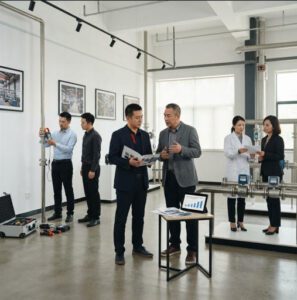
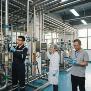
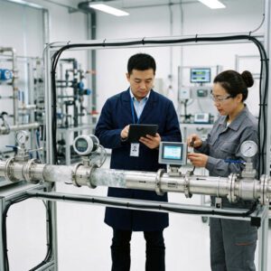
A large-scale chemical processing facility. In environments like this, a single misspecified flow meter on a reactant dosing line can corrupt product quality across hundreds of batches before the root cause is identified.
Understanding Mass Flow Meter Basics
What Mass Flow Meters Measure — and Why Mass Matters in Chemical Processing
Most flow meters measure volumetric flow rate — the volume of fluid passing a point per unit time (m³/h, L/min, GPM). This is adequate for incompressible liquids at constant temperature, but in chemical processes, density is rarely constant. A 20°C swing in a polymer solution changes its density by 1–3%; a batch of concentrated sulfuric acid has a density of approximately 1,840 kg/m³, while a 30% dilution drops to ~1,220 kg/m³. A volumetric meter sees both as the same number of cubic meters — a fundamentally wrong answer for material balance calculations.
A mass flow meter measures the mass of fluid passing per unit time (kg/h, t/h, lb/min) directly, independently of fluid density, temperature, or pressure changes. This is why chemical engineers specify mass flow meters for: (1) reactant dosing where stoichiometry is mass-based, (2) custody transfer where material quantities must match invoices, (3) batch control where recipe accuracy is tied to mass targets, and (4) environmental reporting where emission factors require mass quantities.
📖 Key Terms — Defined on First Use
- Mass flow rate
- The mass of fluid passing a measurement point per unit time (kg/h, t/h). Independent of fluid density, temperature, and pressure — which is why it is the preferred measurement in chemical processes where these variables change.
- Coriolis effect
- The deflection of a moving mass (or fluid) caused by inertial forces when it travels through a rotating or vibrating reference frame. Coriolis flow meters use this principle: vibrating tubes twist in proportion to the mass of fluid flowing through them.
- Turndown ratio
- The ratio of maximum to minimum measurable flow rate at which the meter meets its accuracy specification. A 100:1 turndown means the meter is accurate from 1% to 100% of its rated maximum flow — important for processes with variable production rates.
- Span calibration
- Verification that the meter’s output at the upper end of its measurement range matches a known reference value. Drift in span calibration is a common source of systematic error in chemical plant meters operating at elevated temperatures.
- Zero drift
- A shift in the meter’s output at zero flow conditions, caused by temperature changes, vibration, or mechanical stress on the sensor. Uncorrected zero drift of even 0.01% of full scale on a high-capacity line can represent thousands of kilograms of unaccounted material per day.
- Wetted materials
- The materials of construction that make direct contact with the process fluid — typically the sensor tube, flanges, gaskets, and seals. Incorrect wetted material selection is the most common cause of premature mass flow meter failure in chemical service.
Common Measurement Principles: Coriolis, Thermal, and Differential Pressure
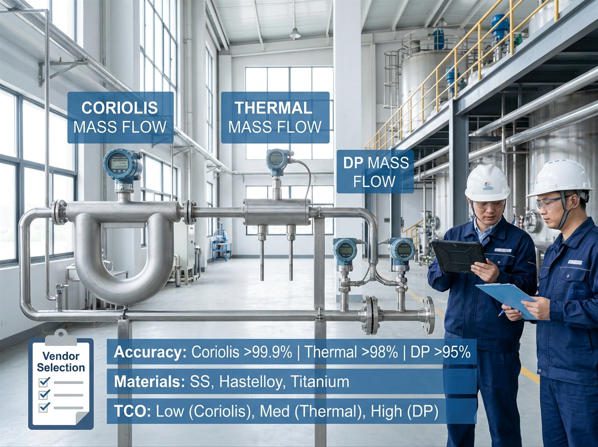
Three measurement principles dominate mass flow measurement in chemical plants. Coriolis meters vibrate a tube and measure how much the flowing fluid twists that vibration — a direct, density-independent measurement of mass flow. Thermal meters heat a sensor and measure how much energy the flowing fluid carries away — a principle that works best for gases where heat capacity is a stable, known property. Differential pressure (DP) meters create a pressure drop across a restriction and infer flow from Bernoulli’s principle — the oldest and most widely installed principle, requiring density compensation to calculate mass.
Typical Installation Environments and Signal Outputs
Chemical plant mass flow meters must operate across a wide range of environmental conditions: ambient temperatures from –20°C to +60°C, process temperatures from cryogenic (–200°C for liquefied gases) to +400°C for hot process streams, pressures from near-vacuum to 400 bar, and hazardous area classifications requiring ATEX or IECEx-certified equipment. Signal outputs are typically 4–20 mA analog (the industry standard for compatibility), with modern transmitters additionally supporting HART, Modbus RTU, PROFIBUS PA, FOUNDATION Fieldbus, and Ethernet APL for integration with DCS and SCADA systems.
Identify Your Process Requirements
Before evaluating any meter technology, document your process envelope with the rigor of an engineering specification — not just the normal operating condition, but the full range including startup, shutdown, minimum turndown, and worst-case excursion scenarios. This discipline eliminates roughly 70% of wrong-technology selections before they happen.
Desired Accuracy, Turndown Ratio, and Response Time
Define accuracy as a business requirement first, then convert to a measurement specification. A pharmaceutical intermediate plant dosing a USD 2,000/kg active ingredient at 50 kg/h needs sub-0.1% mass accuracy — a Coriolis meter with PremiumCal calibration is the only credible choice. A steam utility header serving a general process building where the goal is energy cost allocation to cost centers needs ±2–3% — a DP orifice plate meter is perfectly adequate and 5× cheaper to install.
Turndown ratio is the measurement range divided by the minimum measurable flow at rated accuracy. A chemical plant that runs at 5 t/h during startup and 50 t/h at full production needs 10:1 turndown at minimum. A batch process that idles between batches and peaks at full production may need 100:1 — which immediately rules out standard orifice plates (typically 4:1 to 6:1) and favors Coriolis (up to 100:1) or thermal meters (up to 1,000:1 for gas).
Response time matters for control loops. A fast-acting chemical dosing injection system where the PID controller adjusts feed every 500 ms needs a meter with an update rate of at least 5 Hz and a time constant well under 200 ms. Most Coriolis transmitters update at 10–100 Hz. DP meters with electronic transmitters update at 1–10 Hz. Thermal meters for gases are the slowest, with time constants typically 0.5–5 seconds.
Process Conditions: Pressure, Temperature, and Emissions
| Process Parameter | Data to Document | Impact on Meter Selection |
|---|---|---|
| Temperature | Min / Normal / Max (°C); cycling frequency | Determines sensor tube alloy, transmitter rating, and whether remote electronics are required |
| Pressure | Operating pressure (barg); test pressure; vacuum risk | Governs pressure-class flanges, sensor tube wall thickness, and safety certification |
| Flow range | Min / Normal / Max (kg/h or m³/h) | Drives meter sizing and turndown requirement; determines technology eligibility |
| Fluid state | Liquid / Gas / Steam / Multiphase; phase change risk | Multiphase flow is the most common cause of Coriolis meter error; flashing requires special consideration |
| Hazardous area | Zone 0/1/2 (gas); Zone 20/21/22 (dust); T-class | Requires ATEX/IECEx certification; limits transmitter choices and cable lengths |
| Allowed emissions | VOC emission limits; fugitive emission compliance | Seal selection (welded vs. gasketed) and leak-test documentation requirements |
Chemical Compatibility and Safety Considerations
Chemical compatibility is a multi-layer problem — it is not enough to know the primary process fluid. You must also consider: (1) cleaning chemicals used in CIP/SIP cycles, (2) trace impurities or reaction by-products in the stream, (3) the interaction between the process fluid and the meter materials at operating temperature (many corrosion reactions are exponentially faster at 80°C than at 20°C), and (4) the gasket and seal materials, which are frequently the first components to fail in aggressive chemical service.
Types of Mass Flow Meters for Chemicals
Coriolis Meters: Strengths, Limitations, and Typical Applications
A Coriolis mass flow meter drives one or two sensor tubes into resonant vibration — typically at 50–300 Hz — using electromagnetic drivers. As fluid flows through the vibrating tubes, Coriolis forces cause a phase shift in the vibration: the inlet half of the tube lags the outlet half by a time interval Δt that is directly proportional to mass flow rate. Because the measurement is based on inertial mass — not velocity, not pressure drop, not heat transfer — it is inherently independent of fluid density, viscosity, temperature, and pressure changes.
This is why Coriolis meters are often called the “reference standard” in industrial flow measurement. Emerson’s widely cited technical literature notes that Coriolis meters are routinely used as transfer standards for verifying other meter types — with liquid mass flow accuracy of ±0.10% being common and ±0.05% achievable under optimized calibration conditions. In a chemical plant blending two reactants in a 1:3 mass ratio, that level of accuracy is the difference between a product within specification and a batch that must be reworked at USD 15,000–50,000 per event.
▶ Video: Coriolis Flow Meter Theory of Operation — a clear visual walkthrough of the vibrating tube principle, phase shift measurement, and how density and temperature are simultaneously derived from the same sensor.
Coriolis meters also deliver simultaneous density and temperature measurement from the same instrument — without additional sensors. The vibration frequency of the tube shifts with the density of the fluid inside it; the transmitter converts this to a density reading. For chemical plants where density is a proxy for concentration (e.g., sulphuric acid strength, caustic soda percentage, ethanol content), this second measurement variable transforms a flow meter into an inline quality instrument.
Limitations to plan for: Coriolis meters are sensitive to two-phase flow (entrained gas in a liquid, or liquid droplets in a gas). Even 0.5% gas void fraction in a liquid can cause the vibration to damp, producing erratic or zero output. In chemical processes where pump cavitation, flashing near control valves, or dissolved-gas release is possible, this is a genuine operational risk. Additionally, Coriolis meters require inline installation — no clamp-on option exists — and larger sizes (above DN100) carry a high weight and cost premium that can be difficult to justify for low-accuracy monitoring applications.
Thermal Mass Meters: When to Use and What to Watch For
Thermal mass flow meters measure the rate at which heat is transferred from a heated sensor element to the flowing fluid. The amount of heat removed is proportional to the mass flow rate — specifically, to the product of mass flow rate and the fluid’s specific heat capacity (Cₚ). For gases with a known, stable Cₚ — compressed air, nitrogen, CO₂, natural gas, oxygen — thermal meters provide direct mass flow measurement without any density compensation.
This makes thermal meters the preferred technology for industrial gas metering: compressed air systems, nitrogen purge lines, process gas feeds, biogas, and natural gas. Jade Ant Instruments’ thermal gas mass flow meters are designed specifically for these applications — delivering low pressure loss, high sensitivity at low flow rates, and direct mass output without external pressure and temperature compensation.
The critical limitation: thermal meters are calibrated for a specific gas composition. If the gas composition changes — for example, a natural gas line where the methane fraction varies with supply source — the meter’s apparent specific heat will be wrong, and the mass flow reading will drift proportionally. A 10% shift in gas Cₚ produces a 10% mass flow error if no correction is applied. For mixed or variable-composition gases, inline gas chromatography or a Coriolis meter is a more robust choice.
Differential Pressure and Other Alternatives: Best-Fit Scenarios
Differential pressure (DP) flow measurement creates a deliberate pressure drop across a restriction — typically an orifice plate, venturi tube, or averaging Pitot tube — and uses Bernoulli’s principle to calculate velocity. Because DP meters measure velocity (not mass), mass flow calculation requires density compensation via separately measured temperature and pressure signals. This adds transmitter cost, wiring complexity, and a potential for systematic error if the density calculation assumptions are wrong.
Despite this limitation, DP meters remain widely installed in chemical plants for four pragmatic reasons: (1) their low initial cost — an orifice plate and DP transmitter for a DN150 line costs USD 1,500–3,500 versus USD 8,000–25,000 for a Coriolis meter of equivalent bore; (2) their suitability for steam measurement where Coriolis is impractical; (3) their well-established maintenance practice with in-plant spare parts; and (4) their tolerance for high temperatures (above 200°C) and high pressures (above 100 barg) where Coriolis sensor tube integrity becomes a concern.
The Engineering ToolBox flow meter selection reference provides a useful overview of DP meter configurations and their applicable flow conditions for steam, gas, and liquid service.
Key Performance Characteristics to Compare
Accuracy vs. Repeatability vs. Stability
These three terms are routinely confused in meter specifications and procurement discussions. Accuracy (or linearity) describes how close the meter’s reading is to the true value — the total error including both systematic and random components, expressed as a percentage of reading (% of rate) or percentage of full scale (% of FS). Repeatability describes how consistently the meter gives the same reading when conditions are unchanged — a meter can be repeatable but inaccurate (e.g., ±0.05% repeatable but 2% off the true value due to a calibration offset). Stability describes how the meter’s calibration changes over time under real process conditions.
For chemical plant applications, repeatability often matters more than absolute accuracy in closed-loop control applications: if the meter consistently reads 1.5% high, the controller will compensate once this offset is known. But if the meter reads ±2% randomly, the controller cannot compensate and process variation increases. For custody transfer and material accounting, absolute accuracy is paramount. Specify both — and ask vendors for their meter’s typical stability data (drift per year under process conditions), not just the factory calibration accuracy.
Turndown Ratio, Zero Drift, and Span Calibration Requirements
Zero drift is the change in the meter’s output when true flow is zero — caused by temperature cycling, vibration, or mechanical stress on the sensor element. In a Coriolis meter with a full-scale range of 5,000 kg/h, a zero drift of 0.005% of full scale equals 0.25 kg/h of phantom flow being reported at zero. On a 24/7 process line, that is 2,190 kg/year of material imbalance accumulating silently in the plant’s mass balance ledger.
Best practice is to perform a zero adjustment under process conditions — isolating flow with the meter filled with process fluid at operating temperature and pressure — at commissioning and annually thereafter. Most modern Coriolis and thermal meters support this via a transmitter parameter without removing the meter from the line.
Response Time, Dynamics, and Surge-Prone Lines
Chemical feed lines with positive-displacement metering pumps generate strong flow pulsation. An orifice plate on a pulsating line will over-read by 2–15% due to the non-linear relationship between pressure drop and flow (the “square root error”). A Coriolis meter is inherently immune to moderate pulsation because it measures inertial forces, not pressure drop. For strongly pulsating lines (greater than ±20% of mean flow), a pulsation dampener upstream of any DP meter is essential.
Material Compatibility and Corrosion Considerations

Wetted material selection is the single most consequential decision for long-term Coriolis meter reliability in chemical service. The cheapest material option often becomes the most expensive field outcome.
Wetted Materials and Gasket Choices
The “wetted materials” of a mass flow meter are those that make direct contact with the process fluid: sensor tubes, flow dividers, process connections (flanges), and the gaskets or seals between them. Each of these must resist the specific chemical attack profile of your fluid — not just “corrosion resistance in general.”
| Material | Typical Application in Chemical Service | Key Strength | Key Limitation | Relative Cost Index |
|---|---|---|---|---|
| 316L Stainless Steel | Water, mild acids/bases (pH 4–10), solvents without chlorides | Low cost, wide availability, good general corrosion resistance | Pitting/crevice corrosion in chloride-containing media above 50 ppm | 1× |
| Hastelloy C-276 | HCl, HNO₃, H₂SO₄ (dilute), mixed acids, chlorinated solvents, FeCl₃ | Excellent resistance to oxidizing and reducing acids; chloride tolerant | Not suitable for hot concentrated H₂SO₄ (>80%, >60°C); expensive | 4–6× |
| Titanium (Grade 2) | Seawater, chlorine-containing bleach streams, oxidizing acids, wet chlorine gas | Exceptional resistance to oxidizing chloride environments | Attacked by dry chlorine, fuming HNO₃, and reducing conditions | 5–8× |
| Tantalum | Hot concentrated H₂SO₄ (>80%), HCl at any concentration, chromic acid | Nearly universal acid resistance; matches glass in chemical inertness | High cost; attacked by hot strong alkalis (NaOH >80°C), fluorine | 12–20× |
| PTFE / PFA (lined) | Strong acids, strong alkalis, solvents — non-Coriolis meters (DP, mag) | Widest chemical resistance profile; inert to nearly all chemicals below 150°C | Cannot be used as Coriolis sensor tube material; limited to liner applications | 2–3× (lined) |
| Cost index relative to 316L SS base. Selection should be validated against the manufacturer’s chemical resistance chart at actual operating temperature and concentration, not at ambient conditions. | ||||
Elastomers, Coatings, and Chemical Compatibility Charts
Gaskets and seals are the most frequently overlooked compatibility item. A Hastelloy C-276 Coriolis sensor tube installed with standard EPDM flange gaskets in a concentrated nitric acid service will fail at the gasket interface within months — not at the tube. The gasket material must match the fluid’s chemical aggressiveness at operating temperature. Common gasket materials for chemical service include: PTFE (broadest chemical resistance), FKM/Viton (hydrocarbons, concentrated acids, but not ketones or esters), EPDM (steam, hot water, dilute alkalis, not hydrocarbons), and FFKM/Kalrez (essentially universal but 20–40× the cost of FKM).
Pressure Rating, Temperature Limits, and Cleaning/Maintenance Implications
The published pressure and temperature ratings of a flow meter must both be met simultaneously — not independently. A Coriolis meter rated to 100 barg and 200°C does not necessarily maintain its full pressure rating at 200°C; high-temperature de-rating curves are specified in the product datasheet and must be reviewed for every high-temperature application. For chemical plants subject to periodic CIP cleaning cycles (hot caustic at 80°C, followed by acid rinse), the cleaning fluid compatibility must be verified separately from the process fluid compatibility.
Fluid Properties and Their Impact on Measurements
Density, Viscosity, and Temperature Effects on Meter Types
Viscosity is particularly important for Coriolis meters in heavy chemical service. Very high-viscosity fluids (>1,000 cP) can damp the Coriolis tube vibration, reducing signal strength and increasing measurement noise. Manufacturers specify a maximum viscosity for each model — typically 1,000–5,000 cP for standard designs and up to 20,000 cP for specialized high-viscosity Coriolis meters. For polymer melts, heavy tars, or high-viscosity adhesives, consult the specific product’s viscosity-flow range chart before sizing.
Gas vs. Liquid vs. Multiphase Challenges
Multiphase flow — any combination of gas, liquid, and solid phases — is the most challenging measurement condition in chemical plants. Consider these specific scenarios:
- Entrained gas in liquid (gas void fraction, GVF): Even 0.5% GVF in a liquid can reduce Coriolis meter output to zero or produce erratic readings. Install automatic gas detection and implement process design measures to collapse gas slugs upstream of the meter (e.g., upstream knockout pot or bubble trap).
- Liquid carryover in gas: Liquid droplets in a gas stream affect thermal meter readings because the droplets have a much higher heat capacity than the gas. If liquid carryover is possible, a moisture separator upstream of the thermal meter is recommended.
- Slurries (solid-liquid): Coriolis meters can handle slurries if the solids are uniformly distributed and do not settle in the U-tube geometry. Abrasive slurries (above 5% by volume) cause erosive wear on the inner tube wall over time; straight-tube Coriolis designs are preferred because they drain completely and do not trap solids.
Technology Suitability by Fluid Type — Chemical Plant Applications
Bar length represents relative suitability (longer = better fit). Accuracy figures are indicative; validate against specific product datasheets.
Slurries, Particulates, and Fouling Risks
Fouling — the deposition of scale, polymer, or biological material on the meter’s internal surfaces — is a slow, invisible source of measurement error that typically only becomes apparent during an annual calibration check. For Coriolis meters, scale buildup inside the vibrating tube adds mass to the tube itself, causing the meter to report a higher apparent density and potentially shifting the zero point. The mitigation is a regular zero-verification protocol: if the zero reads outside its commissioning value by more than the specified tolerance (typically ±0.5% of full scale), schedule a cleaning.
Installation and Piping Considerations

A well-engineered meter station includes upstream and downstream isolation valves, a bypass line for maintenance without process shutdown, and proper support to prevent pipe-induced vibration stress on the sensor body.
Piping Layout, Straight-Run Requirements, and Bypass Options
One of the most practical advantages of Coriolis mass flow meters in chemical plant retrofit applications is their minimal straight-pipe requirement. Because the measurement is based on Coriolis forces rather than velocity profile averaging, most Coriolis meters require only 0–5D of straight pipe upstream and 0–3D downstream. By contrast, an orifice plate requires 20–30D upstream depending on the upstream fitting configuration, and a vortex meter typically needs 15–20D upstream.
Thermal meters for gas service typically require 15–20D upstream of straight, undisturbed pipe to ensure fully developed flow across the sensor element. This is a frequent installation challenge in chemical plants where piping runs are dense and straight-run space is at a premium.
Every chemical plant mass flow meter installation should include a bypass line: an upstream isolation valve, a downstream isolation valve, and a bypass valve that allows the process to continue running while the meter is removed for calibration, cleaning, or replacement. Without a bypass, every calibration event requires a process shutdown — a cost that can easily exceed USD 5,000–20,000 per event in a continuous chemical plant.
Vibration, Isolation, and Thermal Effects
Coriolis meters are vibration-sensitive instruments. The sensor tube vibrates at a carefully controlled resonant frequency; external vibration at or near that frequency from nearby pumps, compressors, heat exchangers, or structural resonance can interfere with the measurement signal and cause erratic readings or false alarms. The mitigation approach includes: (1) mounting the meter on a rigid support that is mechanically isolated from vibrating equipment, (2) selecting a meter model with a resonant frequency that is not close to the dominant vibration frequency of the environment, and (3) using the transmitter’s built-in frequency exclusion filter if available.
Thermal stress on the sensor body — from large temperature swings between shutdown and restart — can cause mechanical stress in the flange bolts and in the sensor tube weld joints. In chemical plants with frequent start-stop cycles, specify Coriolis meters with flexible process connections or ensure the pipe supports allow thermal expansion without transmitting stress to the meter body.
Electrical and Signal Integration with Control Systems
The mass flow meter transmitter must communicate with your DCS, PLC, or SCADA system. For new plant construction, HART over 4–20 mA remains the most compatible and cost-effective choice — it preserves analog compatibility with existing control hardware while providing digital diagnostic access. For new DCS projects or plant-wide digitization programs, PROFIBUS PA (intrinsically safe, two-wire) or Ethernet APL (10 Mbit/s, intrinsically safe two-wire) deliver richer diagnostic data and faster update rates. For hazardous area classifications, confirm the transmitter’s ATEX/IECEx approval category against your area classification before specifying communication protocol — some fieldbus protocols require additional barriers that add cost and latency.
Calibration, Validation, and QA
Calibration Frequency and Methods (Traceability, Standards)
Mass flow meter calibration must be traceable to a national metrological standard (NIST in the USA, PTB in Germany, NPL in the UK, NIM in China) through an unbroken chain of documented comparisons. This traceability chain is mandatory for custody-transfer applications and for pharmaceutical GMP compliance, and is strongly recommended for all chemical plant mass flow meters used in material balance calculations.
The ISO 11631 standard for fluid flow measurement defines traceability groups and calibration requirements for flow meters used in fiscal and custody-transfer service. For general chemical plant process meters, ISO 17025-accredited calibration laboratories provide the required traceable certification.
Recommended calibration intervals by application type are typically: every 12 months for custody-transfer and regulatory-compliance meters; every 2–3 years for general process meters with modern self-diagnostic capability; and every 5 years for meters with continuous in-situ verification (e.g., Endress+Hauser Heartbeat Technology, which generates a traceable verification report without removing the meter from service).
In-Situ vs. Bench Calibration: Pros and Cons
| Method | How It Works | Pros | Cons | Best For |
|---|---|---|---|---|
| In-situ verification | Transmitter runs internal self-check algorithms against reference parameters stored at factory calibration | No process shutdown; no meter removal; traceable PDF certificate generated; fast (10–30 min) | Only verifies — does not re-calibrate; requires original factory reference data to be intact | Extending intervals between bench calibrations; ISO 9001 risk-based quality programs |
| On-line proving (master meter) | A calibrated reference (“master”) meter is temporarily installed in series with the process meter | Calibration performed under actual process conditions (correct fluid, pressure, temperature) | Requires a certified master meter, temporary piping, and flow conditions representative of operation | Custody-transfer fiscal meters; situations where bench calibration fluid differs significantly from process fluid |
| Bench calibration (off-site) | Meter removed from process and tested against a calibrated reference flow at a certified laboratory | Highest confidence; complete re-calibration possible; regulatory acceptance for all standards | Requires bypass valve for continuous operation; lead time 1–4 weeks; additional handling cost; calibration fluid may differ from process fluid | Initial calibration; after significant process changes; regulatory compliance points |
Documentation and Change Control Requirements
For chemical plants operating under ISO 9001, ISO 14001, GMP (pharmaceutical), or OSHA PSM (process safety management), the calibration documentation package must include: the calibration certificate with traceability statement, the as-found and as-left data, the calibration equipment identification and certification status, the name and signature of the calibrating technician, and the next due date. Any meter that fails an as-found check (reads outside its specified tolerance before adjustment) must trigger a non-conformance review to assess whether previously reported flow data was affected and whether any process decisions need to be revisited.
Maintenance, Reliability, and Lifecycle Costs
Routine Maintenance Tasks and Common Failure Modes
Coriolis and thermal mass flow meters have no moving parts in contact with the fluid, which eliminates the most common failure mode of velocity-based meters (bearing wear). The dominant failure modes in chemical plant service are:
- Sensor tube corrosion or erosion (Coriolis): Typically manifests as a gradual shift in zero point or density reading. Detection: compare density output against a process lab sample; unexplained density drift of more than 2–5 kg/m³ from expected warrants a tube inspection.
- Sensor element fouling (thermal): Scale or contamination on the heated element raises its apparent thermal resistance, causing under-reading. Detection: compare meter output against a reference measurement (e.g., flow through a known vessel over a timed period). A 5–10% under-read relative to the reference is a typical fouling signature.
- Vibration-induced fatigue at weld joints (Coriolis): The most catastrophic failure mode — a through-wall crack at the tube-to-manifold weld joint releases process fluid. Prevention: correct installation (no pipe stress, no external vibration at resonant frequency) and periodic visual inspection of the sensor body and welds.
- Transmitter electronics failure: Capacitor aging, display degradation, or firmware errors. Typically becomes apparent after 10–15 years of service. Most manufacturers offer transmitter replacement without sensor removal — keeping the calibrated sensor intact while refreshing the electronics.
Spare Parts Strategy and Downtime Planning
A practical spare parts strategy for a chemical plant with 20+ mass flow meters of the same model family: hold one complete sensor spare (the sensor body with tubes — the calibrated component) and two transmitter spares per meter model. This covers a sensor failure (rare but high-consequence) and the more common transmitter failures, without the capital cost of stocking one complete meter per installation point. Ensure the sensor spare is calibrated before it enters the stockroom — a sensor that has never been calibrated is not a useful emergency spare.
Total Cost of Ownership Over Plant Lifecycle
Indicative 10-Year Total Cost of Ownership — DN25 Chemical Service Meter (USD)
Includes CAPEX (meter + transmitter), installation (USD 1,200), calibration (3–5 intervals), maintenance labor, spare parts, and estimated downtime cost (USD 3,000–8,000/event). High-fouling DP service assumes 4 cleaning events over 10 years.
Typical 10-Year TCO Cost Breakdown — Coriolis Meter in Chemical Service
- CAPEX (meter + transmitter) — 38%
- Installation & commissioning — 8%
- Calibration (3–5 intervals) — 22%
- Maintenance labor & parts — 18%
- Downtime & production loss — 14%
Approximate average across Coriolis installations in chemical plant service. Downtime share increases significantly if no bypass is installed (process shutdown required for calibration or maintenance).
Making the Final Selection and Vendor Evaluation

A structured RFQ process — documenting the process envelope, accuracy requirement, material specification, and TCO model before contacting vendors — typically reduces the procurement cycle by 30–40% and eliminates post-order specification disputes.
Request for Information / Quotation Criteria
A well-structured RFQ eliminates the single most common procurement mistake: receiving non-comparable quotations because different vendors interpreted different assumptions. Your RFQ package should specify:
Field Support, Service Network, and Warranty Terms
The quality of vendor support in your geographic region is a practical selection factor that is rarely captured in a datasheet comparison. Ask each shortlisted vendor to confirm: the location and contact details of the nearest authorized service center, the typical response time for emergency field service calls, the availability of replacement sensors in your size and material specification from local stock (not factory-order), and the terms of the warranty with respect to chemical compatibility failures — some manufacturers void warranty if the fluid is outside a specified compatibility list.
For chemical plants in regions where major Western European and American brands have limited local service infrastructure, established ISO-certified manufacturers like Jade Ant Instruments offer an increasingly competitive alternative — providing factory-direct support, OEM/ODM customization for specific chemical applications, and direct communication with manufacturing engineers for non-standard material or pressure ratings. This model is particularly relevant for large new-build plants in Asia, the Middle East, and emerging markets where multi-year service contracts with global brands may be commercially unfavorable.
Risk Assessment and Alignment with Plant Digitalization Goals
Chemical plants investing in digital transformation — Industry 4.0, digital twins, predictive maintenance, and real-time process optimization — need flow meters that are capable partners in that transformation. This means: (1) rich diagnostic outputs that provide early warning of degradation before accuracy is affected; (2) communication protocols that integrate natively with plant historian and asset management systems (PAM); and (3) transmitters that support firmware updates and remote configuration without sending a technician to the field. The five-factor flow meter selection guide from Jade Ant Instruments includes a specific section on digital integration requirements and protocol matching for process control systems.
Complete Technology Comparison: Coriolis vs. Thermal vs. DP
| Characteristic | Coriolis | Thermal Mass | DP (Orifice/Venturi) |
|---|---|---|---|
| Measurement principle | Coriolis inertial force on vibrating tube | Heat transfer from sensor to flowing gas | Bernoulli pressure drop across restriction |
| Measures directly | Mass flow + density + temperature | Mass flow (gas only, known Cₚ) | Volumetric flow → mass (with density comp.) |
| Best accuracy (liquids) | ±0.05 – 0.10% of rate | Not recommended for liquids | ±0.5 – 1.5% of rate (with density comp.) |
| Best accuracy (gases) | ±0.25 – 0.5% of rate | ±0.5 – 2.0% of rate | ±1 – 3% of rate |
| Turndown ratio | Up to 100:1 | Up to 1,000:1 (gas) | 4:1 – 6:1 (standard) |
| Moving parts | None | None | None (orifice plate) |
| Pressure drop | Moderate (0.2–1.5 bar) | Minimal (insertion type) | Significant permanent loss (0.5–2 bar) |
| Applicable fluids | Liquids, gas, slurry, viscous fluids | Gas only (known Cₚ) | Liquid, gas, steam, multiphase (with care) |
| Temperature range | –200°C to +350°C (model-dependent) | –40°C to +500°C (insertion type) | –200°C to +600°C (standard orifice) |
| Two-phase sensitivity | High — GVF >0.5% can cause errors/outage | Moderate — liquid droplets cause error | Moderate — can read with compensation |
| Straight-pipe requirement | 0–5D upstream | 15–20D upstream | 20–30D upstream |
| Typical CAPEX (DN25) | USD 5,000 – 25,000+ | USD 1,500 – 6,000 | USD 800 – 4,000 |
| Calibration interval | 2–5 years (in-situ verification capable) | 1–3 years | 1–3 years (orifice plate replacement) |
| Best-fit chemical applications | Reactant dosing, batch control, custody transfer, mass balance, density measurement | Nitrogen purge, compressed air metering, process gas feeds, biogas, natural gas | Steam headers, high-temperature/pressure gas, utility lines, low-accuracy monitoring |
| Green highlight = strength; amber = conditional advantage; red = limitation. All figures are indicative; validate against specific product datasheets and process conditions. | |||
A Balanced Decision Framework
Selecting the right mass flow meter for a chemical processing plant is a structured engineering decision — not a brand preference or a budget shortcut. The framework is consistent across every application: (1) document the process envelope completely, including extremes and not just normal conditions; (2) match the measurement principle to the physical properties of the fluid; (3) specify wetted materials based on the actual corrosion profile at operating temperature, not ambient data; (4) model the 10-year TCO explicitly, including downtime cost; and (5) validate the selected technology with a pilot installation or vendor demo before full-scale rollout.
Coriolis meters are the highest-confidence choice whenever you need direct mass flow, density, and high accuracy on liquids or gases — and the total cost of measurement uncertainty exceeds the premium cost of the technology. Thermal mass meters are the economical, reliable standard for single-component or known-composition gas measurement where direct mass output without pressure and temperature compensation is required. DP meters remain the pragmatic choice for steam, high-temperature/pressure gas, and low-accuracy utility monitoring where their low capital cost and simple spare-parts story outweigh their turndown and density-compensation limitations.
Before issuing a purchase order for any chemical plant mass flow meter, run a pilot test on your actual process fluid at your actual operating conditions. Vendor-supplied demo meters are available from most reputable suppliers for exactly this purpose — and a 4-week pilot installation that reveals an unexpected measurement artifact is worth far more than the cost of 30 misspecified meters already installed across a new-build plant.
Ready to Specify Your Chemical Plant Mass Flow Meters?
Jade Ant Instruments manufactures ISO 9001-certified Coriolis, thermal, electromagnetic, vortex, and turbine flow meters for chemical processing, water treatment, oil & gas, and industrial applications worldwide. Free technical consultation and custom sizing available.
Request a Free Technical Consultation →Frequently Asked Questions
Click any question to expand the answer.
What are the most common failure modes for mass flow meters in chemical plants?
The most common Coriolis meter failures in chemical plant service are: (1) sensor tube corrosion or erosion — typically caused by incorrect wetted material selection for the actual fluid at operating temperature; manifests as zero-point drift or density reading offset. (2) Two-phase flow damage — entrained gas in a liquid causes the tube vibration to damp violently; repeated gas slug events can fatigue the tube welds over time. (3) Fouling and scaling on the tube interior, causing apparent density drift and zero shift. (4) Vibration-induced fatigue at weld joints — prevented by correct mounting and vibration isolation. For thermal meters, the primary failure mode is sensor element fouling (contamination on the heated tip). For DP meters, it is orifice plate wear, plugging of the impulse lines, and gasket corrosion. A comprehensive failure mode analysis for each technology type is provided by the Sierra Instruments flow meter troubleshooting guide.
How do Coriolis meters compare to thermal meters in terms of maintenance needs?
Both technologies have no moving parts in contact with the fluid, which eliminates bearing wear and mechanical fatigue as maintenance concerns. Coriolis meters require: zero verification under process conditions (annually or after major temperature changes), periodic tube inspection for corrosion in aggressive chemical service, and transmitter diagnostics review. Thermal meters require: sensor element inspection and cleaning when fouling is suspected (typically annually in moderate-contamination gas service), calibration verification against a reference flow (every 1–3 years depending on application), and gas composition checks to verify that the actual gas Cₚ matches the calibration reference. Coriolis meters typically have longer calibration intervals (2–5 years with in-situ verification capability) compared to thermal meters (1–3 years). The critical maintenance differentiator is that Coriolis calibration intervals can be extended using in-situ verification tools — thermal meters generally cannot self-verify to the same standard.
How should I approach calibration if my process involves slurries?
Slurry calibration presents three specific challenges. First, the calibration laboratory must have a flow rig capable of handling your slurry — most standard flow calibration labs use clean water, which is not representative of your actual process fluid density and viscosity. For critical slurry applications, on-line proving (master meter method) using a second calibrated Coriolis meter in series is the most reliable approach. Second, slurry density and composition typically vary between batches, so the calibration condition should represent the “normal” slurry composition rather than any one specific batch. Third, fouling between calibration intervals is common in slurry service; implement a zero-verification protocol (zero check at no-flow with meter filled with slurry at operating temperature) at every planned shutdown to detect fouling-related drift between calibration events. The Tektronix flow meter calibration guide provides a useful framework for setting calibration intervals based on measurement criticality and observed drift history.
Can mass flow meters handle multiphase flows, and what are the limitations?
No mass flow meter technology handles true multiphase flow (simultaneous gas, liquid, and solid phases) reliably without compensation. For each technology: Coriolis meters are highly sensitive to entrained gas — even 0.5–1% gas void fraction can cause error or loss of signal. Some advanced Coriolis transmitters (e.g., Emerson’s Micro Motion advanced LGCS algorithm) can partially compensate for GVF up to ~10%, but this is an exception requiring specific model and firmware configuration. Thermal meters are affected by liquid carryover in gas streams; moisture separators upstream are the standard mitigation. DP meters are affected by density variations in the two-phase stream, which alter the relationship between pressure drop and mass flow. For chemical plant applications with unavoidable two-phase conditions, the best approach is process design — install an upstream knockout drum or de-aeration vessel to separate phases before the meter, rather than trying to compensate for two-phase flow in the meter algorithm.
What factors most influence the total cost of ownership for mass flow meters?
Based on lifecycle cost modeling across chemical plant installations, the five factors with the largest impact on 10-year TCO are: (1) Bypass valve installation (or lack thereof): No bypass means every calibration event requires a process shutdown, costing USD 3,000–20,000 per event depending on production value. A USD 800 bypass station amortizes over 4–5 calibration events in the first 5 years. (2) Wetted material specification: An incorrect material selection that causes premature corrosion failure typically costs 3–10× the original meter cost in replacement, lost production, and investigation. The material premium for Hastelloy C-276 over 316L is USD 3,000–8,000; the cost of a single tube failure is USD 15,000–50,000. (3) Calibration interval management: Using in-situ verification to extend calibration intervals from 1 year to 3 years reduces calibration cost by two-thirds on the same meter. (4) Transmitter diagnostics capability: Meters with advanced self-diagnostics enable condition-based maintenance (calibrate only when drift is detected) versus time-based maintenance (calibrate annually regardless). (5) Supplier service infrastructure: A meter from a supplier with no local service capability effectively adds 4–8 weeks of production downtime risk per unplanned failure versus a supplier with 48-hour field response. For detailed TCO modeling methodology, the Jade Ant Instruments five-factor selection guide provides a step-by-step framework.
What wetted material should I specify for a Coriolis meter measuring concentrated sulfuric acid?
The material specification for sulfuric acid (H₂SO₄) depends critically on concentration and temperature — two variables that interact in ways that are counterintuitive. For concentrations below 60% H₂SO₄ at temperatures below 60°C, 316L stainless steel is generally acceptable (the surface passivates). Above 60% concentration or above 60°C, the passivating layer breaks down and 316L corrodes rapidly — Hastelloy C-276 is the minimum specification. For concentrations above 85% H₂SO₄ at any temperature (e.g., oleum-range), Hastelloy C-276 also becomes marginal; tantalum is the correct specification. At very high concentrations (93–100%), carbon steel paradoxically performs well due to strong passivation, but this is impractical for a Coriolis sensor tube. Always consult the manufacturer’s chemical resistance chart at your specific operating concentration and temperature — not a generic “sulfuric acid” entry. Incorrect material selection in this service is one of the most common and most costly specification errors in chemical plant instrumentation.
How does zero drift affect mass balance calculations in a chemical plant?
Zero drift is one of the most insidious sources of systematic error in chemical plant mass balance because it is silent, continuous, and accumulates over time. Consider a Coriolis meter on a 10,000 kg/h reactant feed line with a full-scale of 15,000 kg/h. A zero drift of 0.01% of full scale = 1.5 kg/h of phantom flow being continuously reported. Over one year at 8,400 hours of operation, that is 12,600 kg of reactant “used” in the plant’s mass balance that was never actually consumed — enough to distort a material efficiency KPI by 0.1–0.5% depending on batch size. The practical mitigation is: (1) specify meters with a zero stability specification (not just zero accuracy — ask for long-term zero stability data over temperature range), (2) perform a zero check under process conditions at every planned shutdown, (3) document the as-found zero before any adjustment and trigger a non-conformance investigation if the zero has drifted outside tolerance.
Is it possible to use a single Coriolis meter for multiple fluids in a multipurpose chemical plant?
Yes — this is one of Coriolis technology’s strongest advantages over thermal meters. A Coriolis meter measures mass flow directly from inertial forces, independent of fluid density, viscosity, or composition. The same meter can accurately measure water, 30% NaOH, 98% H₂SO₄, and toluene in sequence without reconfiguration, provided: (1) the wetted materials are compatible with all fluids in the rotation — verify each chemical separately at operating temperature; (2) the flow ranges of all fluids fall within the meter’s specified range for the required accuracy; (3) the fluid is always single-phase (no gas entrainment, no vapor lock) during any measurement period; and (4) adequate flushing between fluids is performed if cross-contamination would affect measurement or product quality. For multipurpose reactors that alternate between chemistries, this flexibility makes a single installed Coriolis meter more cost-effective than installing technology-specific meters for each fluid type.
What ATEX certification should I require for a mass flow meter in a Zone 1 hazardous area?
For a Zone 1 hazardous area (flammable gas or vapor present intermittently in normal operation), the transmitter must carry an ATEX certification of at minimum II 2G Ex d IIC T-class (explosion-proof housing) or II 2G Ex ia IIC T-class (intrinsically safe). The T-class (T1–T6) must be selected based on the Auto-Ignition Temperature (AIT) of the flammable substance in the atmosphere: T6 (<85°C surface temperature) is required for flammables with AIT below 85°C (e.g., some ethers); T4 (<135°C) covers most common solvents and hydrocarbons. The sensor body itself in contact with process fluid is typically not separately ATEX-certified — the hazardous area protection applies to the electrical components of the transmitter. For installations where sensor and transmitter are mounted separately (common in high-temperature applications), both must be individually certified for the area classification. Verify the exact ATEX code and T-class on the product certificate — do not rely on a product brochure statement of “ATEX approved” without reviewing the certificate details.
How do I evaluate whether a Coriolis meter vendor’s accuracy claim is credible?
Vendor accuracy claims require four critical filters before acceptance. First, confirm the accuracy is expressed as % of rate (reading), not % of full scale — a ±0.5% of full-scale claim on a meter running at 10% of full scale is actually ±5% of reading. Second, confirm the accuracy applies at your operating flow rate, not at the vendor’s reference flow rate (which is typically 50–80% of full scale where all meters perform best). Third, confirm the calibration is traceable to a national standard (NIST, PTB, NPL) through an ISO 17025-accredited laboratory — and request the calibration certificate to verify. Fourth, ask for the zero stability specification (not just zero accuracy) over your operating temperature range — a meter with excellent rate accuracy but poor zero stability will give systematically wrong totalized flow at low-flow conditions. Reputable manufacturers including those reviewed in the Jade Ant Instruments mass flow meter brand comparison guide provide all four of these data points on request.