Choosing the wrong flow meter isn’t just a technical inconvenience — it can quietly drain thousands of dollars per year in calibration failures, unplanned downtime, and inaccurate billing. This guide cuts through the marketing noise and gives you a data-backed, side-by-side comparison of three of the most widely deployed technologies.
Overview of Water Meter Technologies
Walk into any industrial facility, municipal water plant, or agricultural irrigation hub, and you’ll find flow meters quietly doing the work of measurement — counting every liter, cubic meter, or gallon that passes through the pipe. Yet the wrong choice of meter technology can cost you far more than the meter itself. A propeller meter that clogs in a sludge-laden channel, a paddle wheel that drifts 5% off calibration after six months, or an electromagnetic meter installed without grounding on a plastic pipe — any of these create billing errors, regulatory headaches, or process upsets that compound month after month.
This guide focuses on three of the most common flow-measurement technologies used in water management, light industrial, and commercial applications: the propeller meter, the paddle wheel meter, and the electromagnetic (EM) meter. Each operates on a fundamentally different physical principle, and those differences directly determine which one is right for your pipe, your fluid, and your budget.

Flow meters on industrial pipelines — the right technology choice depends on fluid type, flow range, and installation conditions.
Propeller Meter: Basic Concept and Typical Applications
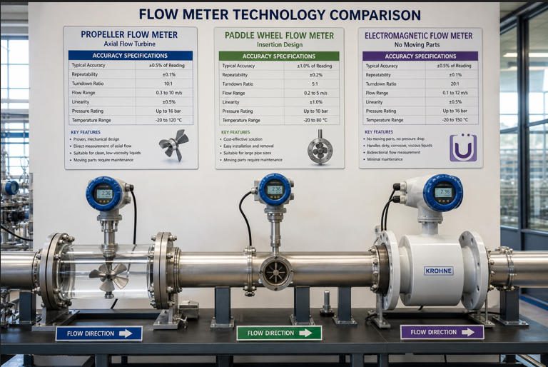
A propeller meter — sometimes called a turbine propeller meter — places a multi-bladed rotor directly in the full cross-section of the pipe. As water flows, it pushes against the blades and spins the propeller; the rotational speed is directly proportional to flow velocity. Because the propeller sweeps nearly the entire pipe bore (unlike turbine meters, which use smaller inline rotors), it accurately captures the full velocity profile. Propeller meters have been the standard in agricultural irrigation and municipal water distribution for decades. According to McCrometer, one of the leading propeller meter manufacturers, these meters are deployed across agriculture, fire protection, drinking water treatment, and wastewater channels worldwide.
Paddle Wheel Meter: Basic Concept and Typical Applications
A paddle wheel meter inserts a small rotating wheel — equipped with flat or angled paddles — into the flow stream, typically through the side or top of the pipe. Only a portion of the paddles contact the flowing liquid at any given moment, making it inherently a sample-velocity measurement rather than an area-averaging one. This makes paddle wheel meters among the most cost-effective options for clean water, treated water, and water-like fluids in residential and commercial settings. Their simple design means they can be inserted into pipes with minimal pipe modification, but that same simplicity introduces sensitivity to flow profile disturbances.
Electromagnetic Meter: Basic Concept and Typical Applications
An electromagnetic (EM) meter — also called a magmeter or magnetic flow meter — contains no moving parts whatsoever. Instead, it applies Faraday’s Law of Electromagnetic Induction: two coils generate a magnetic field perpendicular to the flow, and the conductive fluid moving through that field induces a small voltage proportional to its velocity. The fluid itself becomes the “rotor.” This makes EM meters exceptionally suitable for conductive fluids including municipal water, wastewater, chemical process streams, slurries, and food-grade liquids. The global electromagnetic flowmeter market was valued at approximately USD 3.99 billion in 2025 and is projected to reach USD 5.33 billion by 2030, growing at a 5.9% CAGR — reflecting their dominant position in industrial flow measurement (Mordor Intelligence).
How Each Meter Measures Flow
Propeller Meter: Mechanical Rotation and Interpretation of Flow
The propeller’s rotation is detected by a reed switch, Hall-effect sensor, or magnetic pickup mounted in the meter body. Each revolution — or a fixed number of pulses per revolution — is converted by the meter’s register into a flow rate and cumulative total. Because the propeller spans essentially the full pipe bore, the measurement is an excellent area-average of the velocity profile, making propeller meters more tolerant of moderate flow disturbances than point-velocity sensors. The rotational signal is linear over a wide flow range, and the mechanics are rugged enough to handle field conditions without sophisticated electronics. The tradeoff is straightforward: anything that interferes with rotation — debris, sand, corrosion of the bearing — directly degrades measurement quality.
Paddle Wheel Meter: Turbine-Based Measurement and Signal Processing
In a paddle wheel meter, small magnets are embedded in the paddle wheel blades. As the wheel rotates, these magnets pass a Hall-effect or reed-switch sensor mounted externally, generating a pulse train that the transmitter converts to flow rate. Since the paddle only samples a strip of the velocity profile — typically at the pipe centerline — the reading is sensitive to the shape of the velocity profile. A straight-pipe run of 10–20 pipe diameters upstream is usually required to ensure the profile is fully developed and symmetrical, otherwise the meter will read high or low depending on where the disturbance is located. Signal conditioning in modern paddle wheel transmitters applies filtering algorithms to smooth out pulse irregularities, particularly at low flow velocities where the wheel may rotate erratically.
Electromagnetic Meter: Faraday’s Law and Conductive Fluid Measurement
The physics underlying EM meters is elegant in its simplicity. When a conductive fluid (minimum conductivity ≥ 5 µS/cm) moves through a magnetic field generated by coils in the meter body, a voltage E is induced across two electrodes flush-mounted in the pipe wall. That voltage is described by Faraday’s Law:
where E = induced voltage, B = magnetic field strength, L = electrode distance (pipe diameter), v = fluid velocity
Because the relationship is strictly linear — double the velocity, double the signal — EM meters provide inherently linear output with no mechanical wear. The transmitter converts the millivolt signal into a 4–20 mA analog output, pulse output, or digital protocol (HART, PROFIBUS, Ethernet APL). No pressure drop is created since the full bore remains unobstructed. The only hard constraint is fluid conductivity: hydrocarbons, deionized water, and organic solvents cannot be measured by standard EM meters.
▶ Recommended Watch: “How To Select a Flow Meter — Mechanical vs. Magnetic” — a concise visual breakdown of how propeller-type and electromagnetic meters approach the same measurement challenge differently.
Accuracy and Reliability
Factors Affecting Accuracy for Propeller Meters
Propeller meters are rated at ±2% of actual rate over their full operating range, with repeatability of ±0.25% under stable conditions (McCrometer data sheet). In practice, three factors most frequently push them outside that specification. First, incomplete pipe fill: if the pipe is even partially empty — common in pressurized irrigation lines that drain and refill — the meter reads incorrectly because flow rate calculations assume full-bore conditions. Second, bearing wear: in water carrying sand or fine grit (common in agricultural groundwater), the stainless-steel bearings gradually wear, increasing rotational drag and causing under-reading — often 5–8% low after two to three seasons of heavy use. Third, flow profile distortion: bends, valves, or reducers within 5–10 pipe diameters upstream create asymmetric velocity profiles that the propeller cannot average correctly, introducing errors of 2–4%.
Factors Affecting Accuracy for Paddle Wheel Meters
Standard paddle wheel meters deliver ±1% to ±3% of reading under ideal conditions; the KOBOLD USA technical specification more conservatively cites ±2.5% to ±5% as the typical field range. The primary accuracy risk is the same as for propeller meters — flow profile — but it is amplified because the paddle samples only a thin strip rather than the full bore. A 90-degree elbow immediately upstream can bias readings by 8–12% in lab tests. The second risk is low-flow dropout: paddle wheel meters typically stop registering accurately below approximately 0.3 m/s, meaning intermittent or low-flow processes may go unrecorded or show erratic readings. In one commercial HVAC installation that one of our engineers reviewed, a paddle wheel meter showed a persistent 6.5% over-reading traced entirely to a tee fitting installed 4 pipe diameters upstream — a problem corrected by moving the meter 15 pipe diameters further downstream with no hardware cost.
Factors Affecting Accuracy for Electromagnetic Meters
Properly installed EM meters achieve ±0.2% to ±0.5% of reading, placing them in a different accuracy tier from mechanical meters. A 2024 analysis of 1,247 EM meter service tickets found that 50% of all field failures traced to improper grounding — not hardware defects. Another 20% involved electrode coating (fouling) and 15% related to partial pipe fill (Soaring Instrument, 2024). When grounding is correct and the pipe is full, EM meter accuracy is remarkably stable: a properly maintained EM meter typically shows less than 0.1% drift per year, meaning calibration intervals can extend to 3 years or longer under ISO 20456 guidelines.
📊 Accuracy Comparison: Best-Case vs. Typical Field Performance (%)
Lower % = better accuracy. “Typical field” reflects real-world installation conditions.
Sources: McCrometer, KOBOLD USA, Soaring Instrument, KOBOLD technical datasheets. Field performance assumes realistic installation conditions without ideal straight-run requirements.
Typical Installation Requirements
Site Considerations Common to All Meters
Regardless of technology type, all three meter families share a fundamental requirement: full-pipe flow at the measurement point. A pipe that is partially empty — whether due to air pockets, inadequate system pressure, or intermittent flow — will cause every technology to read incorrectly. Beyond this baseline, each technology introduces its own installation constraints that must be designed into the piping layout before the first weld is made, not retrofitted after commissioning.
Propeller and Paddle Wheel: Piping Layout and Susceptibility to Flow Profile
Both mechanical meter types are sensitive to upstream flow disturbances because they infer total flow from a velocity reading. Standard installation guidelines specify 10–15 pipe diameters (D) of straight run upstream and 5D downstream of any elbow, valve, pump outlet, or pipe size change. For paddle wheel meters, some manufacturers require up to 20D upstream when a double-bend or partially open valve is present.
Propeller meters are generally more forgiving than paddle wheel meters in this regard because the full-bore propeller naturally averages across a wider velocity profile. However, a severe asymmetric profile — caused by a 90-degree bend immediately upstream — can still introduce 3–5% error even in propeller meters. Installation in vertical pipes with upward flow eliminates the risk of air accumulation and is the preferred orientation wherever space permits.
Electromagnetic: Electrical Grounding and Conductive Fluid Requirements
EM meters require significantly less straight run than mechanical meters — typically 5D upstream and 2–3D downstream — but introduce a critical requirement that mechanical meters do not: proper electrical grounding. The induced voltage signal is in the millivolt range; without a low-impedance path to earth, stray electrical currents from variable frequency drives (VFDs), welding equipment, or cathodic protection systems can swamp the signal, creating measurement offsets of 5–25%.
💡 Real-World Case: The €180 Fix
A food-processing plant in the Netherlands reported persistent 8–12% flow-reading fluctuations on an EM meter installed on an HDPE pipeline. Three vendor service calls totaling €4,200 found no hardware defect. A fourth technician identified the root cause: no grounding rings on the plastic pipe flanges. Installing grounding rings on both flanges and connecting them to the plant earth bus reduced fluctuations to below 0.3% — within minutes. Total grounding-ring cost: €180.
For metallic pipes with good electrical continuity, the pipe itself can serve as the grounding path. For plastic, rubber-lined, or FRP pipes, grounding rings (also called earthing rings) made of stainless steel or the same metal as the electrodes must be installed on both the upstream and downstream flanges. A detailed installation guide published by Aister Meter Engineering covers every grounding scenario for split and compact EM meter designs.

Proper piping layout — straight runs, orientation, grounding — determines whether even the best meter performs in the field.
| Requirement | Propeller Meter | Paddle Wheel Meter | EM Meter |
|---|---|---|---|
| Upstream Straight Run | 10–15D | 15–20D | 5D |
| Downstream Straight Run | 5D | 5D | 2–3D |
| Preferred Orientation | Horizontal or Vertical Up | Horizontal (electrode horizontal) | Vertical Up or Horizontal |
| Grounding Required | No | No | Yes (critical) |
| Full Pipe Required | Yes | Yes | Yes |
| Fluid Conductivity Needed | None | None | ≥5 µS/cm |
| Pipe Cutting Required | Yes (inline) | Insertion (hot-tap possible) | Yes (inline) |
Maintenance and Longevity
Maintenance Needs for Mechanical Meters (Propeller and Paddle Wheel)
Mechanical meters have moving parts, and moving parts wear. For propeller meters used in agricultural irrigation, the most common maintenance task is bearing inspection and replacement, typically required every 3–5 years in clean water, but as frequently as annually in sandy or gritty water. The propeller itself may need replacement after heavy debris events (leaves, twigs, stones) that chip or bend the blades. A bent propeller blade throws the rotor out of balance, causing vibration-induced bearing wear and flow-reading errors that can reach 10–15% before the fault is detected. Paddle wheel meters face similar wear on the wheel axle pins and bearings, and the paddles themselves can develop calcium scaling or biofilm buildup in warm-water applications that progressively slows the wheel and causes under-reading.
The industry reality is that most mechanical meter failures are slow — the meter doesn’t suddenly stop working, it gradually drifts out of specification. In a municipal water billing system, a 3% drift on 10,000 meters translates to millions of cubic meters of unbilled water annually. Most water utilities operating propeller meters schedule annual field calibration checks and bench testing every 3–7 years depending on water quality.
Maintenance Needs for Electromagnetic Meters
Because EM meters have no moving parts, their primary maintenance focus shifts from mechanical wear to electrode condition and liner integrity. In clean water applications, EM meters can run for 5–10 years without any intervention beyond an annual signal check. In wastewater or chemical service, electrodes can develop coating from suspended oils, fats, or mineral scale that attenuates the signal and causes under-reading. Modern EM meters address this with built-in self-diagnosis: Endress+Hauser’s Heartbeat Technology, for instance, continuously monitors coil resistance and electrode impedance and flags coating buildup before it affects measurement accuracy. A properly maintained EM meter from Jade Ant Instruments or a comparable manufacturer is rated for 15–25 years of service life in normal water service — compared to 3–7 years for typical mechanical meters in the same application (Soaring Instrument, 2024).
Calibration and Service Intervals
Calibration intervals should be driven by application risk, not arbitrary schedules. For custody-transfer billing (water utilities, chemical plants), annual in-situ verification is the practical standard, with full bench calibration every 3 years. For process monitoring without billing implications, a 3–5 year interval is appropriate for EM meters in clean water — provided the meter’s self-diagnostic system shows no drift indicators. Mechanical meters used for irrigation management should be calibrated at the start of every growing season if water rights are being managed, because accumulated bearing wear through the previous season may have shifted the meter 2–4%.
Common Advantages by Application
Residential and Small Commercial Scenarios
For residential water metering and small commercial buildings (up to DN50 / 2-inch pipe), paddle wheel meters are the dominant choice — and with good reason. They cost $50–$300 per point, install easily into standard PVC or copper pipe, and deliver accuracy within 2–3%, which is adequate for billing at residential scales where individual consumption typically ranges from 5 to 50 m³/month. A 2% billing error at those volumes represents less than $5/month per household — an acceptable variance in most utility rate structures. The simplicity of the design also means that a plumber with basic instrumentation training can install, replace, or troubleshoot a paddle wheel meter without specialized equipment.
Commercial and Industrial Scenarios with Higher Flow Demand
As pipe diameter grows from DN50 to DN100 and above, and as flow rates reach thousands of liters per hour, the economics shift decisively toward electromagnetic meters. Consider a food and beverage plant processing 500 m³/day of process water. A 2% metering error translates to 10 m³/day of unbilled or incorrectly allocated water — about 3,650 m³/year. At commercial water rates of $1.50–$4.00 per m³, that’s $5,500–$14,600/year in measurement error. An EM meter at ±0.2% accuracy reduces that error to $550–$1,460/year, paying for its price premium often within the first year of operation. This pattern repeats across chemical dosing, HVAC chilled-water loops, and municipal distribution mains where flow measurement directly drives billing, process control, or regulatory compliance.
Special Considerations: Dirty Water, Slurry, and Multi-Chemical Streams
For fluids containing suspended solids, abrasives, or corrosive chemicals, electromagnetic meters hold a structural advantage: the full-bore design means there are no moving parts, rotors, or narrow passages to clog, erode, or corrode. EM meters routinely handle conductive slurries with 30–40% solids by weight — a regime that would destroy a paddle wheel in weeks and heavily erode a propeller bearing in months. The key selection variables for dirty-service EM meters are liner material (polyurethane for abrasive slurries, PTFE for corrosive chemicals) and electrode material (Hastelloy C-276 for mixed acids, titanium for chlorinated media, tantalum for extreme chemical service). For a detailed liner and electrode selection matrix, the electromagnetic flow meter selection guide from Jade Ant Instruments maps over 40 chemical compounds to compatible liner-electrode combinations.
Limitations and Vulnerabilities
Susceptibility to Debris and Wear (Propeller and Paddle Wheel)
Any physical object inserted into a flowing stream will eventually be affected by what that stream carries. For propeller meters, the threat is mechanical impact and abrasion: a single stone larger than the gap between blades can stall or fracture the propeller, causing complete measurement failure rather than gradual drift. In open-channel irrigation, strainers or screens upstream of propeller meters are mandatory — not optional — and screen maintenance becomes a recurring operational cost that many buyers fail to include in their total cost of ownership estimates. Paddle wheel meters are somewhat protected by their insertion geometry (only part of the wheel enters the stream), but they remain vulnerable to fibrous material (algae, vegetation) wrapping around the axle, bringing the wheel to a complete stop.
Electrical and Magnetic Interference Considerations (EM Meters)
While EM meters have no mechanical vulnerabilities, they introduce an electrical one. The measurement signal is inherently small — on the order of millivolts — and can be overwhelmed by stray electrical currents from variable frequency drives, welding arcs, cathodic protection rectifiers, or even nearby high-voltage power cables. In plants with heavy VFD usage (common in energy-efficient pump control systems), inadequate cable separation and shielding is the single most frequently cited cause of EM meter noise. The remedy is well-established: dedicated shielded signal cable rated to the manufacturer’s specification, single-point grounding at the transmitter, and physical separation of signal cables from power cables by at least 300 mm. EM meters also cannot measure non-conductive fluids — hydrocarbons, deionized water below 1 µS/cm, or organic solvents — a fundamental physical limitation that no amount of engineering workaround can overcome.
Fluid Properties and Installation Constraints
Each meter type has a fluid property boundary beyond which it becomes unreliable or fails entirely. Propeller and paddle wheel meters require clean-to-moderately-clean water; they cannot handle high-viscosity fluids because the drag force on the rotor changes the velocity-to-rotation relationship. Electromagnetic meters require conductivity ≥ 5 µS/cm and are incompatible with oils, gasoline, diesel, and most organic solvents. Installation constraints — available straight run, pipe material, access for maintenance — must be assessed before any technology is selected, because a technically superior meter installed in the wrong piping environment will consistently underperform a simpler meter installed correctly.
📊 Root Causes of Flow Meter Field Failures (n = 1,247 service tickets, 2024)
50% — Improper Grounding (EM meters)
20% — Electrode Coating / Fouling
15% — Partial Pipe Fill / Air Pockets
10% — Mechanical Wear (bearing / rotor)
5% — EMI / Signal Cable Issues
Source: Soaring Instrument, 2024 field-service analysis across water, wastewater, and chemical industries.
Cost Considerations and Total Cost of Ownership
Purchase Price and Availability
The sticker-price hierarchy is clear and consistent across the industry. Paddle wheel meters for standard pipe sizes (DN15–DN50) are available for $50–$400 per measurement point — the most accessible tier. Propeller meters scale with pipe diameter: a DN50 propeller meter runs $200–$500, while DN200–DN600 agricultural irrigation meters from established manufacturers such as McCrometer can reach $1,500–$4,000 per unit. Electromagnetic meters occupy the widest price range: entry-level DN50 EM meters from ISO-certified manufacturers start around $300–$600, while precision versions from major European brands (Endress+Hauser, KROHNE, ABB) for the same size range from $2,200 to $4,500. For large-bore industrial applications (DN200 and above), EM meters from these premium suppliers can reach $8,000–$20,000 per unit, though ISO-certified manufacturers like Jade Ant Instruments supply comparable-accuracy EM meters at 30–50% lower acquisition cost, making them a practical option for large-scale installations where purchase budget is constrained.
Installation, Wiring, and Integration Costs
Purchase price is only the beginning of the financial picture. Installation costs for mechanical meters are primarily pipe work: cutting, flanging, and alignment, typically $200–$600 per point for an experienced pipefitter. EM meters add an electrical component: grounding conductors, shielded signal cable, and power supply routing, adding $300–$800 per point in typical industrial settings. However, EM meters require less straight-run piping to be built or modified, which can offset or reverse this cost advantage in retrofit projects where creating 20D of straight run for a mechanical meter would require significant pipe relocation. SCADA integration costs are comparable across all three technologies for analog (4–20 mA) output; digital protocol integration (HART, PROFIBUS, Modbus) is most common with EM meters, which typically include these outputs as standard.
Maintenance, Calibration, and Replacement Costs
This is where the TCO story often inverts the purchase-price ranking. Over a 10-year operational horizon, an EM meter’s higher purchase price is frequently recovered through lower maintenance and replacement costs. A propeller meter in agricultural service may need bearing replacement ($80–$150 parts, $200 labor) every 3–5 years, propeller replacement ($150–$300) every 7–10 years, and a full bench calibration ($200–$400) every 3 years — totaling $1,200–$2,000 per meter over 10 years in maintenance alone, before counting any downtime cost. An EM meter in the same application may require only one electrode inspection and calibration check over the same period, at a total maintenance cost of $400–$800 for a standard unit.
| Cost Category (10-Year Horizon) | Propeller Meter (DN100, Irrigation) | Paddle Wheel Meter (DN50, Commercial) | EM Meter (DN100, Municipal Water) |
|---|---|---|---|
| Purchase Price | $800–$1,500 | $200–$400 | $1,200–$3,000 |
| Installation (pipe + electrical) | $400–$700 | $200–$400 | $600–$1,200 |
| Calibration (3 intervals) | $600–$1,200 | $300–$600 | $600–$1,200 |
| Bearing/Rotor/Electrode Maintenance | $800–$1,500 | $400–$800 | $200–$500 |
| Estimated Downtime Cost | $800–$2,000 | $400–$1,000 | $200–$600 |
| 10-Year TCO (Estimated) | $3,400–$6,900 | $1,500–$3,200 | $2,800–$6,500 |
| Expected Service Life | 5–10 years | 3–7 years | 15–25 years |
💡 Industry Insight
A turbine/propeller meter that costs $4,000 and lasts 15 years comes to approximately $267/year of service. But when you factor in the 2–3% measurement error that compounds across millions of cubic meters of billed flow, the financial cost of imprecision dwarfs the service cost. In a municipal system distributing 5 million m³/year, a 2% meter error represents 100,000 m³ of unbilled water — potentially $150,000–$400,000 in annual revenue leakage. That context reframes the TCO conversation entirely. (Turbines, Inc. — TCO Analysis)
How to Choose the Right Meter for Your Situation

Systematic meter selection — starting with fluid characterization and ending with TCO modeling — prevents the specification errors that cause 80% of field failures.
Matching Flow Range and Accuracy Requirements
Start with two numbers: your minimum expected flow rate and your maximum expected flow rate. The ratio between these two values is the turndown ratio — one of the most under-specified parameters in meter selection. A paddle wheel meter typically delivers 10:1 turndown at best; propeller meters offer 15:1 to 30:1; EM meters regularly achieve 100:1 or better, meaning they can accurately measure flows that vary by two orders of magnitude. If your process runs a fire suppression line that is mostly idle but must accurately measure a sudden surge at full-bore flow, or an irrigation system that varies from trickle-irrigation to flood-filling, the turndown ratio alone may make EM meters the only viable option.
For accuracy requirements: billing applications typically need ±2% or better; process control benefits from ±0.5% or better; simple monitoring may tolerate ±3–5%. Match these requirements honestly against the real-world field accuracy data — not the best-case laboratory specification — for each technology. The five-factor flow meter selection framework from Jade Ant Instruments provides a structured worksheet for translating accuracy needs into technology shortlists.
Environment, Fluid Properties, and Maintenance Expectations
Three fluid properties drive technology selection more than any other factor: cleanliness (presence of solids, fibrous material, or debris), conductivity (required for EM meters), and chemical aggressiveness (determines liner and electrode material for EM meters, or corrosion-resistant coatings for mechanical meters). For a clean, low-conductivity fluid like deionized water or a food-grade oil, propeller or paddle wheel meters are appropriate and often optimal. For any conductive fluid with solids content above 0.1% by volume, EM meters are strongly preferred. For corrosive chemicals, the choice is almost exclusively EM meters with appropriate liner-electrode pairing.
Maintenance expectations must also be realistic. A remote agricultural pumping station with no on-site technicians needs a meter that requires annual attention at most — pointing toward EM meters. A municipal water treatment plant with an instrumentation team and well-stocked parts inventory can manage more frequent mechanical meter maintenance if the purchase budget justifies it.
Lifecycle Cost and Compatibility with Existing Systems
Build a 10-year TCO model before finalizing any meter selection. The model should include purchase price, installation labor, calibration frequency and cost, expected maintenance events and their cost, and an estimated downtime cost per event. In chemical plants, a single unplanned meter replacement during a production run typically costs $5,000–$15,000 in lost production — an amount that can justify upgrading from a $500 mechanical meter to a $2,000 EM meter with built-in diagnostics. Also assess protocol compatibility: if your DCS uses HART or PROFIBUS, confirm the meter’s transmitter natively supports those protocols rather than requiring a $500–$1,500 converter per point. The complete flow meter selection guide from Jade Ant Instruments includes a protocol-matching section for SCADA, DCS, and BMS integration.
✅ Choose Propeller Meter When:
- 🌾 Large-bore agricultural or irrigation pipes (DN100–DN600+)
- 💧 Clean water with low solids content
- 📐 Need for full-bore measurement averaging
- 🔧 Robust construction for outdoor field conditions
- 💰 Budget constraints on large-diameter meters
✅ Choose Paddle Wheel When:
- 🏠 Residential or small commercial clean-water metering
- 📏 Small to medium pipe sizes (DN15–DN80)
- 🔌 Easy retrofit without major pipe work
- 💵 Lowest initial cost is the primary driver
- 📊 Monitoring (not billing-critical) applications
✅ Choose EM Meter When:
- 🏭 Industrial, municipal, or chemical process service
- 🧪 Conductive fluid with solids, slurry, or chemicals
- 📈 Billing-critical or regulatory accuracy required
- ⚙️ No moving parts needed for low-maintenance service
- 📡 HART/PROFIBUS digital integration required
Quick Reference Checklist
Summary of When to Choose Each Meter Type
No single flow meter technology is universally superior. The propeller meter is a rugged, cost-effective workhorse for large-bore, clean-water applications where full-bore averaging matters — particularly agriculture and municipal distribution. The paddle wheel meter earns its place in small-pipe, clean-water installations where simplicity and low cost are paramount and billing precision is not the primary concern. The electromagnetic meter is the precision instrument of choice for any conductive fluid where accuracy, reliability, and low maintenance matter more than acquisition cost — which covers the vast majority of industrial, municipal, and chemical process applications.
Quick Decision Criteria Checklist
- Define fluid conductivity first. Below 5 µS/cm: EM meter is not viable. Use propeller or paddle wheel, or consider ultrasonic.
- Assess solids content. Above 0.5% volume fraction: mechanical meters degrade rapidly. EM meter with polyurethane or ceramic liner is preferred.
- Calculate turndown ratio. Max flow ÷ min flow. Above 30:1 → EM meter required. 10:1 to 30:1 → propeller viable. Below 10:1 → paddle wheel possible.
- Map available straight run. Less than 10D upstream → EM meter only. More than 15D → all three viable.
- Determine pipe material. Non-metallic pipe + EM meter = grounding rings mandatory. Budget accordingly.
- Identify accuracy requirement. Billing/regulatory → EM meter (±0.2–0.5%). Process monitoring → propeller or paddle wheel acceptable (±2–3%).
- Model 10-year TCO, not just purchase price. Include calibration, maintenance, downtime, and replacement costs.
- Confirm protocol compatibility with existing DCS/SCADA. Verify the transmitter natively outputs required protocol before ordering.
Final Considerations and Next Steps
The specification phase is where the vast majority of flow meter problems are either created or prevented. A meter that is correctly selected, properly installed, and systematically maintained will deliver accurate data for 15–25 years. One that is mismatched to its fluid, undertightened on grounding, or left uncalibrated will quietly erode the financial and operational value it was bought to create.
If you’re evaluating meters for a new project or a retrofit, the most productive starting point is a systematic fluid characterization: document your fluid’s conductivity, solids content, chemical composition, operating temperature and pressure range, and expected flow range (minimum, normal, maximum). With that data in hand, technology selection becomes a logical elimination rather than a guessing game. For a free engineering consultation, the team at Jade Ant Instruments — an ISO 9001-certified flow meter manufacturer offering electromagnetic, turbine, vortex, and ultrasonic meters — provides application-specific recommendations based on real process data, not catalog defaults.
📖 Key Terms Glossary
- Faraday’s Law of Electromagnetic Induction
- The physical principle behind EM meters: a voltage is induced in a conductor (the flowing fluid) when it moves through a magnetic field. The induced voltage is proportional to the fluid velocity.
- Turndown Ratio (Rangeability)
- The ratio of maximum to minimum measurable flow rate within the meter’s accuracy specification. A 100:1 turndown means the meter can accurately measure from 1 L/min to 100 L/min, for example.
- Pipe Diameter (D)
- Used as a unit of length for specifying straight-run requirements. “10D upstream” means 10 times the pipe’s inner diameter of straight, undisturbed pipe before the meter.
- Liner
- The internal coating of an electromagnetic flow meter that protects the meter body from the process fluid. Common materials: hard rubber, PTFE, PFA, polyurethane, ceramic.
- Electrode
- Small metal discs flush-mounted in the liner of an EM meter that pick up the flow-induced voltage signal. Material must resist the chemical attack of the process fluid.
- Grounding Ring (Earthing Ring)
- A metal ring installed at the EM meter flange face on non-conductive pipes to provide the electrical connection between the fluid and the plant earth bus, preventing stray-current interference.
- µS/cm (Microsiemens per Centimeter)
- The unit of electrical conductivity used to assess whether a fluid is compatible with EM meter measurement. Tap water is typically 300–800 µS/cm; deionized water may be below 1 µS/cm.
- 4–20 mA Output
- The standard analog signal used by most industrial flow meters to communicate with control systems. 4 mA represents zero flow, 20 mA represents full-scale flow.
- HART Protocol
- Highway Addressable Remote Transducer — a digital communication protocol overlaid on the 4–20 mA analog signal, allowing remote configuration, diagnostics, and multi-variable data transfer.
Key Takeaways
- Propeller meters excel in large-bore clean-water applications (agriculture, municipal distribution) where full-bore averaging and ruggedness matter more than sub-1% accuracy.
- Paddle wheel meters are cost-effective for small-pipe, clean-water monitoring where billing precision is not critical and installation simplicity is valued.
- Electromagnetic meters are the right choice for any conductive fluid where accuracy (±0.2–0.5%), long service life (15–25 years), and zero-maintenance moving parts justify a higher upfront cost.
- 50% of EM meter field failures trace to improper grounding — a specification and installation problem, not a product defect. Grounding rings cost <$200; the field service calls to diagnose the resulting errors cost $2,000–$5,000.
- Always model 10-year TCO — not just purchase price — to find the true lowest-cost option for your application lifecycle.
- Use a structured flow meter selection guide that starts with fluid characterization and ends with protocol compatibility, not the other way around.
❓ Frequently Asked Questions
1. What are the typical lifespans of propeller, paddle wheel, and electromagnetic flow meters?
2. Can propeller, paddle wheel, or EM meters be retrofitted into existing pipe systems?
3. How does dirty water or debris affect each meter type differently?
4. Are there any certifications or standards to look for when buying a flow meter?
5. What is the minimum fluid conductivity required for an electromagnetic flow meter to work?
6. Which flow meter type is best for agricultural irrigation applications?
7. How often should flow meters be calibrated, and what happens if calibration is skipped?
8. Can electromagnetic flow meters measure non-conductive fluids like oils or deionized water?
9. What is the difference between a propeller meter and a turbine flow meter?
10. How do I calculate the total cost of ownership (TCO) for a flow meter selection decision?

Modern water treatment facilities use all three meter technologies across different process stages — the right choice at each point depends on the fluid, the flow range, and the accuracy requirement.