
A single poorly matched flow meter on a custody transfer point in an oil pipeline can generate measurement errors worth $50,000–$200,000 per year in lost product accounting, according to field data from upstream operators in the Permian Basin and North Sea. The consequences extend beyond financial loss: inaccurate flow data in safety-critical systems can mask leak conditions, distort process mass balances, and trigger regulatory non-compliance under API MPMS Chapter 5 metering standards.
Oil — whether it is light crude at 2 cP, heavy bitumen at 10,000 cP, refined diesel fuel, hydraulic fluid, or synthetic lubricant — presents a unique set of challenges for flow measurement that water-focused meters simply cannot address. Viscosity varies by orders of magnitude across oil types and temperatures. Entrained gas, wax deposition, sand content, and hydrogen sulfide (H₂S) exposure impose material and design constraints that eliminate entire meter families from consideration. And in upstream and refining environments, most installation points are classified as hazardous areas (Zone 1 or Zone 2 per IEC 60079-10-1), requiring ATEX or IECEx certified equipment.
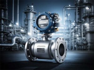
This guide walks through the complete workflow — from characterizing the oil and defining measurement objectives through technology selection, sizing, installation planning, commissioning, calibration, and lifecycle management. It reflects field engineering practices used across refineries, offshore platforms, pipeline terminals, and industrial lubrication systems. Where relevant, we reference specific product capabilities and technical resources from Jade Ant Instruments, whose ISO-certified turbine, electromagnetic, vortex, and ultrasonic flow meter portfolio has been deployed across oil and gas, chemical, and water utility applications spanning more than 12,000 installations worldwide.
Safety and compliance considerations thread through every section of this guide because, in oil applications, instrumentation decisions are inseparable from process safety management. Selecting the wrong wetted material in a sour crude service can cause catastrophic sensor failure within 90 days. Installing a meter without proper grounding in a Zone 1 area creates an ignition risk. These are not hypothetical scenarios — they are documented field failures that this guide is designed to help you avoid.
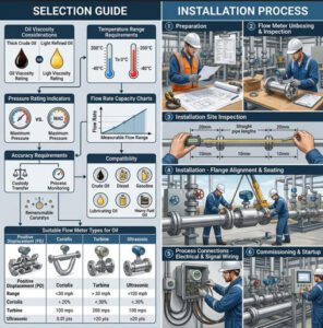
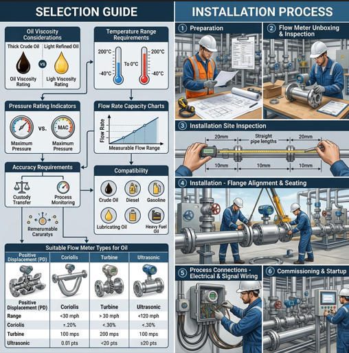
Understanding the Application Requirements

Identify Process Fluid Properties: Oil Type, Viscosity, Density
Every flow meter selection for oil begins with a detailed fluid characterization. The word “oil” covers a spectrum so broad that specifying “oil service” on a meter requisition is roughly as useful as writing “liquid” — it tells the supplier almost nothing about what the meter will actually encounter.
Start with the specific oil type: is this light crude oil (API gravity >31°, viscosity 2–10 cP at process temperature), medium crude (API 22–31°, 10–100 cP), heavy crude (API <22°, 100–10,000+ cP), refined diesel (1.5–4.0 cP), lubricating oil (30–1,500 cP depending on grade), hydraulic fluid (15–100 cP), or heat transfer oil (1–5 cP at operating temperature)? Each of these fluids behaves differently inside a flow meter — and each demands a different technology approach.
Viscosity is the single most consequential fluid property for meter selection in oil applications. A turbine meter that produces ±0.25% accuracy on a light distillate at 3 cP may degrade to ±3–5% on a heavy lube oil at 500 cP because the increased drag on the rotor fundamentally alters the relationship between flow velocity and rotational speed. Conversely, a positive displacement (PD) meter that struggles with slip errors at low viscosity actually improves in accuracy as viscosity increases — the thicker fluid reduces internal leakage between the gears or rotors, tightening the seal between measurement chambers.
Density is critical for mass flow calculations and for sizing. Crude oils range from 700 kg/m³ (light condensate) to 1,000+ kg/m³ (extra-heavy bitumen). If you need mass flow output — standard in custody transfer per ISO 20456 — you either need a meter that measures mass directly (Coriolis) or one that measures volume with a separate density input for compensation.
Define Operating Conditions: Temperature, Pressure, Flow Range
Document the full operating envelope — not just the normal steady-state values, but the extremes the meter will see during startup, shutdown, cleaning, and process upsets. In a crude oil pipeline, operating temperature may range from 5 °C (winter ambient in northern latitudes) to 65 °C (heated heavy crude transport). The viscosity difference between those temperatures can be 20:1 or more, which means the meter’s performance characteristic shifts dramatically between seasonal conditions.
Pressure ratings must account for maximum allowable working pressure (MAWP) including surge conditions. A pipeline that operates at 15 bar steady-state may see 25 bar during pump start or valve closure transients. The meter’s ASME or PN pressure class must cover the surge case, not just the normal operating pressure. For offshore and high-pressure wellhead applications, Class 600 or Class 900 flanged connections may be required.
Flow range definition follows the same logic as pressure: specify minimum, normal, and maximum flow rates including transient conditions. A lubrication oil system that runs at 200 LPM during normal production may drop to 15 LPM during idle periods and spike to 350 LPM during a process sequence change. The meter must deliver acceptable accuracy across this full range — and the turndown ratio (max/min) determines which technologies qualify. A helpful engineering reference for matching flow range to meter type is available in Jade Ant Instruments’ 5-factor selection guide.
Determine Measurement Objectives: Accuracy, Reliability, Maintenance Window
Different measurement points in an oil facility have fundamentally different accuracy requirements. Custody transfer — where money changes hands based on the meter reading — typically demands ±0.15% to ±0.5% of reading, traceable to national metrology standards, with monthly or quarterly proving per API MPMS Chapter 4 (Proving Systems). Process control applications that feed a PID loop for blending or ratio control can often tolerate ±1–2% but require excellent repeatability (±0.1–0.25%) so the control algorithm receives stable, consistent input signals.
Environmental and regulatory reporting points — emissions-related fuel consumption monitoring, waste oil discharge tracking — typically require ±2–5% accuracy but must have documented calibration traceability and tamper-evident data logging.
Maintenance window constraints are equally important. In a 24/7 refinery with annual turnaround cycles, the meter must operate reliably for 12 months between service opportunities. A technology that requires quarterly bearing replacement (like a turbine meter in abrasive crude service) is fundamentally incompatible with a plant that only provides maintenance access once per year. These operational realities should drive technology selection before price is considered.
Types of Flow Meters Suitable for Oil
Primary Element Options: Turbine, Coriolis, Positive Displacement, Ultrasonic, Differential Pressure
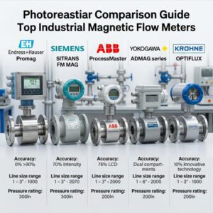
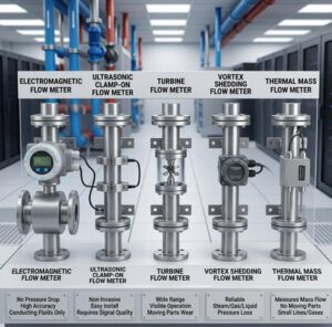
Five flow meter families dominate oil measurement across the global petroleum and industrial lubricant sectors. Each operates on a different physical principle, and that principle determines the meter’s natural strengths and limitations when handling the viscosity, density, and chemical characteristics of oil fluids.
Turbine flow meters place a free-spinning rotor in the flow path. As oil passes through, the rotor spins proportionally to flow velocity. A magnetic pickup converts rotation into a frequency output. In light, clean oil services (diesel, kerosene, light hydraulic fluids below 10 cP), turbine meters deliver ±0.25–0.5% accuracy with excellent repeatability. They are widely used in fuel dispensing and loading rack metering per API standards. However, accuracy degrades rapidly as viscosity increases above 30 cP because the rotor drag becomes a non-linear function of fluid properties rather than flow velocity.
Coriolis flow meters pass fluid through vibrating tubes. The Coriolis effect creates a phase shift between inlet and outlet sensors proportional to mass flow rate. This direct mass measurement eliminates the need for density compensation — a significant advantage for crude oil with variable API gravity. Coriolis meters achieve ±0.1% of reading or better and are insensitive to viscosity changes, making them the technology of choice for custody transfer of crude oil, condensate, and liquid petroleum products. Their limitation in oil applications is pressure drop (which increases with viscosity) and susceptibility to entrained gas — even 2–3% gas void fraction can destabilize the tube vibration and cause measurement errors.
Positive displacement (PD) meters — including oval gear, rotary vane, and oscillating piston designs — trap discrete volumes of fluid and count them mechanically. PD meters are the only technology that actually improves in accuracy as oil viscosity increases. At viscosities above 50 cP, internal leakage (slip) between the rotating elements decreases, tightening the volumetric seal and improving measurement precision. PD meters routinely achieve ±0.1–0.5% on heavy oils at 500–10,000 cP where every other technology struggles. Their weakness is sensitivity to particulate — sand, wax crystals, or pipe scale can damage or jam the internal gears. For applications involving heavy crudes, residual fuels, and industrial lubricants, PD meter technology remains the workhorse of the oil industry.
Ultrasonic flow meters (transit-time type) measure the time difference between acoustic pulses sent with and against the flow. In clean, homogeneous oils, multi-path ultrasonic meters achieve ±0.15–0.5% accuracy and are widely used in pipeline custody transfer for light and medium crudes. They have no moving parts, introduce minimal pressure drop, and can handle very large pipe sizes (DN600+) where other technologies become impractical or prohibitively expensive. Their limitation with oil is that high viscosity attenuates the acoustic signal, and entrained gas or wax deposition can scatter or block the ultrasonic path.
Differential pressure (DP) meters — orifice plates, venturi tubes, and flow nozzles — measure the pressure drop across a restriction to calculate flow. They are the oldest and most widely installed technology in oil facilities, primarily because of their simplicity, low purchase cost, and the extensive engineering standards (ISO 5167, API MPMS Chapter 14) that govern their design and installation. However, DP meters have a square-root relationship between flow and pressure that limits rangeability to about 3:1 with acceptable accuracy. The permanent pressure loss from an orifice plate also represents an ongoing energy cost — at high viscosities, this pressure drop increases substantially.
Video: 6 Common Flow Meter Types Explained — Principles & Applications (RealPars, 2026)
Pros and Cons for Oil Applications (Viscosity Sensitivity, Maintenance Needs)
| Parameter | Turbine | Coriolis | Positive Displacement | Ultrasonic (Transit-Time) | DP (Orifice) |
|---|---|---|---|---|---|
| Accuracy | ±0.25–1.0% | ±0.05–0.1% | ±0.1–0.5% | ±0.15–0.5% | ±0.5–2.0% |
| Repeatability | ±0.1% | ±0.05% | ±0.05% | ±0.1% | ±0.1% |
| Turndown Ratio | 10:1 to 20:1 | 80:1 to 200:1 | 10:1 to 50:1 | 25:1 to 100:1 | 3:1 to 5:1 |
| Viscosity Range | <30 cP optimal | 1–10,000+ cP | 1–100,000+ cP | <300 cP typical | Any (but ΔP increases) |
| Moving Parts | Yes (rotor, bearings) | No (vibrating tubes) | Yes (gears/rotors/pistons) | No | No (but impulse lines) |
| Pressure Drop | Moderate | Moderate–High at high viscosity | Moderate–High | Negligible | High (permanent loss) |
| Entrained Gas Tolerance | Poor | Poor (>2% GVF) | Good (up to 5–10%) | Fair (multi-path) | Fair |
| Maintenance | Medium–High | Low | Medium | Low | Medium |
| Purchase Cost (DN50) | $500–$2,000 | $5,000–$15,000 | $1,500–$5,000 | $2,000–$8,000 | $800–$2,500 |
| Best Oil Application | Light fuels, diesel, kerosene | Custody transfer, crude oil | Heavy oil, lube oil, fuel oil | Pipeline crude (light–medium) | General process monitoring |
Key Selection Criteria for Oil Flow Meters
Accuracy, Turndown Ratio, and Repeatability
The accuracy grade you specify should match the financial and operational consequence of measurement error. In custody transfer — where 0.1% error on a 100,000 barrel/day pipeline at $70/barrel represents $70,000 per day — Coriolis or PD meters with ±0.1–0.15% accuracy and traceable proving are the only defensible choices. On a lube oil recirculation system where the measurement informs a trend display, ±2% from a DP orifice plate costs $2,500 installed and provides all the data resolution needed.
Turndown ratio deserves special attention in oil applications because many oil processes have wide flow variation. A refinery charge heater oil system may run at 800 m³/h during full production and drop to 80 m³/h during turndown — a 10:1 ratio that eliminates DP meters (3:1 effective range) and challenges turbine meters at the low end. Coriolis meters at 200:1 and ultrasonic meters at 100:1 handle this envelope from a single installation point.
Materials, Corrosion Resistance, and Chemical Compatibility
Wetted material selection in oil service is driven by three factors: the base oil chemistry (sweet vs. sour, naphthenic vs. paraffinic), the contaminants present (H₂S, CO₂, chlorides, produced water), and the process temperature. For sweet crude and refined products, 316L stainless steel is the baseline material — adequate for most services and well-characterized in terms of long-term corrosion performance.
Sour crude (>0.5% H₂S by weight) and sour gas applications require materials that resist sulfide stress cracking (SSC) per NACE MR0175 / ISO 15156. This typically means specifying Hastelloy C-276 or Duplex stainless steel for wetted components. In refinery applications handling caustic soda (NaOH) in desalter circuits or sulfuric acid in alkylation units, Hastelloy, Monel, or tantalum may be required. Seal materials must also be compatible — standard Buna-N O-rings degrade in aromatic solvents (toluene, xylene), requiring FKM (Viton) or FFKM (Kalrez) upgrades.
For a structured approach to matching materials to fluid chemistry, the Jade Ant Instruments flow meter selection guide provides a compatibility matrix for common industrial fluids.
Operating Temperature/Pressure Ratings and Seals
Oil processing temperatures range from cryogenic (LNG at -162 °C) to extremely high (thermal cracking furnace oil at 400+ °C). Standard flow meter electronics typically operate to 80 °C ambient; above that, remote transmitter mounting with an extension cable is required. For the sensor itself, Coriolis tubes in 316L stainless are rated to approximately 200 °C; Hastelloy tubes extend to 350 °C. PD meters with carbon or ceramic internal components can handle 300+ °C in certain configurations.
Pressure ratings follow ASME B16.5 flange classes. The majority of oil applications fall within Class 150 (20 bar at 200 °C) to Class 600 (100 bar at 200 °C). Wellhead and high-pressure injection applications may require Class 900 or Class 1500 — a specification that limits technology choices primarily to small-bore Coriolis and PD meters, as turbine and ultrasonic meter housings are not commonly available above Class 600.
Sizing, Data Validation, and Calculations
Estimating Flow Range and Head Loss
Meter sizing for oil applications requires viscosity-corrected calculations that go beyond the simple pipe-diameter matching used in water service. The Reynolds number — which determines whether flow is laminar, transitional, or turbulent — is dramatically lower for viscous oils at the same velocity. A DN50 pipe carrying water at 2 m/s has Re ≈ 100,000 (fully turbulent). The same pipe carrying lube oil at 200 cP and 2 m/s has Re ≈ 900 (fully laminar). Turbine meters require turbulent flow (Re > 4,000–10,000) to maintain their calibration curve; in laminar flow, the K-factor becomes viscosity-dependent and the meter requires viscosity correction or recalibration at the actual operating conditions.
Head loss (pressure drop) through the meter is a critical sizing parameter in oil systems because it directly affects pump energy consumption. For a PD meter on heavy fuel oil at 500 cP, the pressure drop at rated flow may reach 2–4 bar — requiring the system pump to deliver that additional head continuously. Over a 10-year operating period at average electricity rates, a 3-bar pressure drop through a DN100 PD meter at 50 m³/h represents approximately $8,000–$15,000 in cumulative pump energy cost. This cost must be included in the total cost of ownership comparison alongside purchase price and maintenance.
Typical Pressure Drop at Rated Flow (DN50, Heavy Oil at 200 cP)
0
1.0
2.0
3.0
4.0
5.0
Pressure Drop (bar)
0.8 bar
2.5 bar
3.5 bar
0.1 bar
4.2 bar
Turbine
Coriolis
PD
Ultrasonic
DP Orifice
Conditions: DN50, rated flow, heavy oil at 200 cP, 0.92 SG
Impact of Viscosity and Temperature on Meter Performance
Viscosity is not a constant in oil applications — it changes with temperature according to an exponential relationship described by the Walther equation (ASTM D341). A lube oil that measures 320 cP at 20 °C may drop to 32 cP at 80 °C — a 10:1 viscosity change that fundamentally alters the meter’s operating regime. At 320 cP, the flow through a DN50 pipe at typical velocities is laminar, and a turbine meter requires viscosity correction. At 32 cP and the same flow rate, the flow may be transitional or turbulent, placing the turbine meter back in its normal operating envelope.
This temperature-viscosity dependency means that startup conditions — when oil is cold and viscous — represent the most challenging measurement scenario. A custody transfer meter calibrated at 60 °C operating temperature may read 3–5% high during a cold-start at 15 °C if viscosity compensation is not active. Coriolis meters handle this automatically (mass flow measurement is independent of viscosity). PD meters handle it inherently (higher viscosity improves accuracy). Turbine and ultrasonic meters require real-time viscosity compensation, typically derived from a temperature measurement and a stored viscosity-temperature curve.
Installation Planning and Site Considerations

Piping Configuration, Straight-Run Requirements, and Orientation
The standard straight-run guidance for flow meters — 10 pipe diameters upstream and 5 downstream (10D/5D) from any disturbance — is a starting point, not a guarantee. In oil applications, the Reynolds number is often lower than in water service, which means velocity profiles take longer to develop into a stable, fully developed shape. At Re < 2,000 (laminar flow), the profile is parabolic and highly sensitive to upstream disturbances; some meter technologies require up to 20D upstream in laminar conditions.
The table below summarizes straight-run requirements for each technology in oil service:
| Meter Type | Upstream (after single elbow) | Upstream (after double elbow in different planes) | Downstream | Flow Conditioner Alternative |
|---|---|---|---|---|
| Turbine | 15D | 25D | 5D | Yes — reduces to 5D + conditioner |
| Coriolis | 0D (none required) | 0D | 0D | Not needed |
| PD | 0–5D | 0–5D | 0D | Not typically needed |
| Ultrasonic (multi-path) | 10D | 20D | 5D | Yes — reduces to 5D + conditioner |
| DP (Orifice plate) | 20–44D (per ISO 5167) | 44D+ | 5–8D | Yes — reduces to ~10D |
Meter orientation matters in oil service. Horizontal installation is standard for most meter types, but for applications where entrained gas is possible, mounting with the meter slightly inclined (3–5° upward) or fully vertical (upward flow) prevents gas pockets from collecting in the measurement section. PD meters should always be installed with the flow direction arrow aligned correctly — reversed installation can cause immediate mechanical damage to the internal gears or rotors.
Electrical Grounding, Grounding Methods, and EMI Considerations
Proper grounding is both a measurement accuracy requirement and a safety requirement in oil applications. Electromagnetic flow meters are particularly sensitive to grounding — an impedance imbalance between the two measurement electrodes creates a common-mode voltage that the transmitter interprets as a flow signal, producing a false offset. In steel piping with cathodic protection (common in oil facilities), stray currents can create grounding issues unless the meter is isolated with grounding rings or grounding electrodes at each flange.
For hazardous area installations (Zone 1 or Zone 2), the grounding system must also satisfy the requirements of the protection concept — whether that is flameproof (Ex d), intrinsic safety (Ex i), or increased safety (Ex e). IS barriers or galvanic isolators in the control room must be properly matched to the meter’s electrical parameters. Jade Ant Instruments’ installation best practices guide covers grounding configurations for both electromagnetic and vortex meters in hazardous area applications.
Isolation, Sampling Points, and Accessibility for Maintenance
Every inline flow meter in oil service should be installed between isolation valves (block valves) to enable removal for maintenance or calibration without draining the entire pipeline. For custody transfer meters that require periodic proving, the piping design must include a prover connection (or space for a portable prover) between the meter and the downstream block valve. ANSI/API RP 551 provides guidance on meter station piping layout including drain, vent, and sample connections.
Accessibility planning is often the difference between a 4-hour meter change and a 48-hour ordeal. Allow sufficient headroom above the meter for crane or chain hoist access. Ensure flanged connections (not welded) are specified for meters in the DN50–DN300 range so the meter can be unbolted rather than cut out. For large-bore meters (DN400+), permanent lifting lugs and davit arm sockets should be engineered into the meter support structure.
Installation Steps and Best Practices
Pre-Install Checks and Footprint Planning
Before the meter arrives on site, verify that the pipe spool is built to the correct dimensions: inside diameter (matching the meter’s bore), flange rating, face type (raised face or ring-type joint), bolt pattern, and face-to-face length. A common field error in oil applications is receiving a pipe spool with a slight internal diameter mismatch — even a 1–2 mm step at the flange gasket seating area creates a flow disturbance that degrades measurement accuracy and can cause gasket blowout at high pressure.
Confirm that the pipe is clean internally — free of weld slag, mill scale, rust, and construction debris. In oil service, any loose debris will pass through the meter during first fill and can jam PD meter gears, nick turbine rotor blades, or scratch Coriolis tube walls. A pre-commissioning flush with clean fluid (at low pressure, bypassing the meter if possible) is standard practice on new installations.
Mounting, Alignment, and Wiring/Communication Setup
Align the meter’s flow direction arrow with the actual flow direction. Torque flange bolts to the gasket manufacturer’s recommended values using a calibrated torque wrench and a star pattern sequence. For gasket selection in oil service, spiral-wound gaskets with 316SS windings and flexible graphite filler (ASME B16.20, Class CG) are standard for most temperatures and pressures. In high-temperature applications above 450 °C, high-nickel-alloy windings may be required.
Route signal cables in dedicated instrumentation cable trays, separated from power cables by at least 300 mm per ISA-RP12.06.01 recommendations. For hazardous area installations, use armored cables with appropriate gland entries rated to the zone classification. Connect the cable shield at the transmitter end only (single-point grounding) to avoid ground loops. For digital communication (Modbus, HART), verify polarity on RS-485 connections — reversed polarity on Modbus will cause communication failure that is often misdiagnosed as a hardware fault.
Calibration Framing and Initial Verification Procedures
After mechanical and electrical installation, perform an initial zero verification. For Coriolis and electromagnetic meters, this requires filling the meter with the process fluid, ensuring all air is evacuated, and verifying zero flow conditions with both block valves closed. The transmitter’s auto-zero function establishes the baseline from which all flow measurements are referenced. On a Coriolis meter, a zero offset of more than 2× the manufacturer’s specification (typically 0.002–0.01% of full scale) indicates an installation stress, entrained gas, or mechanical vibration problem that must be resolved before proceeding.
For turbine and PD meters, initial verification involves running the meter at a known flow rate — either against a master meter in series, a gravimetric prover, or a volumetric pipe prover — and confirming that the meter factor (K-factor for turbine, or correction factor for PD) falls within the manufacturer’s stated tolerance. Record the as-found meter factor as the baseline for future calibration trending.
Video: Liquid & Gas Measurement — 4 Types of Flow Meters for Oil and Gas (Kimray, 2022)
Commissioning, Testing, and Validation
System Integration Checks: SCADA/HMI Interfacing, Alarms, and Data Logging
Before declaring the meter “in service,” verify end-to-end signal integrity from the sensor through the transmitter, across the cable, through any IS barriers or junction boxes, into the DCS/PLC input card, and up to the SCADA/HMI display. Perform a 4–20 mA loop check by injecting known current values at the transmitter and verifying that the control system reads the corresponding engineering unit value correctly. For digital communications (Modbus RTU), use a portable Modbus master (laptop with USB-to-RS485 adapter) to poll the meter’s register map and confirm that flow rate, totalizer, density (if Coriolis), and diagnostic status words are all reading correctly.
Configure alarms for high flow, low flow, empty pipe detection (electromagnetic meters), drive gain warnings (Coriolis meters), and signal quality degradation (ultrasonic meters). Set data logging intervals — typically 1-second for process control, 1-minute for monitoring, and event-triggered for alarm conditions. Ensure that the historical data system retains at least 12 months of trend data for calibration drift analysis and regulatory compliance.
Baseline Calibration, Span Checks, and End-to-End Verification
Baseline calibration at commissioning establishes the “birth certificate” for the meter installation. For custody transfer applications, this means performing a full proving run per API MPMS Chapter 4 — typically 5 consecutive proving runs with a repeatability of ±0.02% or better, yielding a meter factor that is recorded in the flow computer. For process metering, a span verification against a reference instrument (master meter, clamp-on ultrasonic, or portable Coriolis) at 3–5 flow points across the operating range provides sufficient baseline data.
Document everything: as-found meter factor, calibration date, reference instrument ID and calibration traceability, ambient and process conditions during calibration, and the identity of the calibration technician. This documentation package forms the foundation of the meter’s lifecycle records and must be maintained per your facility’s quality management system (typically ISO 9001 or API Q1).
Maintenance, Calibration, and Lifecycle Management
Routine Inspection, Cleaning, and Part Replacement
Maintenance requirements vary dramatically by technology. The table below summarizes routine maintenance activities for each meter type in oil service:
| Activity | Turbine | Coriolis | PD (Oval Gear) | Ultrasonic | DP Orifice |
|---|---|---|---|---|---|
| Visual inspection | Monthly | Quarterly | Monthly | Quarterly | Monthly |
| Bearing replacement | 12–24 months | N/A | 24–36 months | N/A | N/A |
| Internal cleaning | 6–12 months | As needed | 6–12 months | 12–24 months | 6–12 months (impulse lines) |
| Seal/gasket replacement | 24 months | 36–60 months | 24 months | N/A | 12–24 months |
| Transmitter diagnostics check | 6 months | 12 months | 6 months | 12 months | 6 months |
| Full calibration verification | 6–12 months | 12–36 months | 12–24 months | 12–24 months | 6–12 months |
For turbine meters in crude oil service, wax deposition on rotor blades is a common problem that progressively shifts the meter factor. Periodic removal and cleaning — or in-situ flush with heated solvent — is required to maintain accuracy. PD meters in heavy oil with particulate require periodic strainer inspection upstream and internal gear or rotor examination for wear marks, scoring, or debris accumulation.
Calibration Intervals and Records Management
Calibration intervals should be established based on a combination of regulatory requirements, process criticality, and historical performance data — not arbitrary schedules. The industry standard starting point is annual calibration for custody transfer meters (per API MPMS) and 1–3 years for process meters. However, the best practice approach is to trend the as-found calibration data over successive calibration cycles. If a meter consistently shows less than 0.05% drift between annual calibrations after 3 consecutive years, extending the interval to 18 or 24 months is technically justified and reduces lifecycle cost.
Calibration records must be retained for the life of the meter and include: as-found data (before adjustment), as-left data (after adjustment), reference standard identification and traceability to NIST or national equivalent, environmental conditions during calibration, and the calibration technician’s identity. For ISO 17025 accredited calibration, uncertainty analysis documentation is also required. The Jade Ant Instruments calibration guide provides step-by-step procedures including zero-check methods, span verification protocols, and grounding troubleshooting for electromagnetic meters in challenging field conditions.
Safety, Regulations, and Quality Assurance

Oil Safety Standards, Hazardous Area Considerations, and Permits
Oil processing facilities are classified as hazardous areas per IEC 60079-10-1 (gas hazards) and IEC 60079-10-2 (dust hazards). The vast majority of flow meter installation points in upstream production, pipeline transport, and refining operations fall within Zone 1 (explosive gas atmosphere likely during normal operation) or Zone 2 (explosive gas atmosphere not likely during normal operation but possible during upset conditions). All flow meters installed in these zones must carry ATEX (European Directive 2014/34/EU) and/or IECEx certification appropriate to the zone classification, gas group (IIA, IIB, or IIC), and temperature class (T1–T6).
The protection concept matters: intrinsically safe (Ex ia/ib) meters limit the electrical energy in the hazardous area circuit to below ignition levels — safe and simple, but limited to low-power transmitters. Flameproof (Ex d) enclosures contain any internal explosion within the housing — robust but heavy and requiring proper maintenance of the flame path. Increased safety (Ex e) prevents sparks and hot surfaces by design — suitable for junction boxes and some transmitter housings. Many modern flow meters use a combination: Ex d sensor housing with Ex i signal connections.
Before installation, obtain the necessary hot work permits, confined space entry permits (if applicable), and verify that the site’s area classification drawing confirms the zone classification at the meter location. Post-installation, ensure that the cable gland entries are correctly made with certified cable glands, that unused cable entries are sealed with certified blanking plugs, and that the complete loop (from sensor through cable through barrier to DCS) is documented as compliant with the site’s hazardous area dossier.
Quality Management, Traceability, and Supplier Qualifications
Supplier qualification for oil and gas flow meters goes beyond ISO 9001 certification. Many operators and EPCs (Engineering, Procurement, and Construction contractors) require compliance with API Q1 (Specification for Quality Management System Requirements for Manufacturing Organizations for the Petroleum and Natural Gas Industry) or API Q2 (for service providers). These standards add oil-and-gas-specific requirements for design validation, risk assessment, management of change, and traceability of materials and calibration.
Material traceability per EN 10204 Type 3.1 or 3.2 certificates is standard for pressure-retaining components in oil service. The meter body, flanges, and any wetted parts in contact with the process fluid must have mill certificates tracing back to the specific heat of material. For sour service applications, NACE MR0175 compliance documentation — including hardness test reports — is required for all wetted metallic components.
Jade Ant Instruments maintains ISO 9001 quality management certification across its manufacturing operations and provides EN 10204 Type 3.1 material certificates, ATEX/IECEx documentation packages, and factory acceptance test (FAT) reports as standard deliverables for oil and gas project orders.
Root Causes of Flow Meter Failures in Oil Applications (Industry Survey)
Installation
Errors 35%
Wrong Meter 25%
Material 15%
Calibration 15%
Process 10%
Installation errors
Wrong selection
Material
Calibration drift
Process upsets
The chart above — derived from field failure analysis data reported by major oil operators — reveals that 60% of flow meter failures originate from human decisions (installation errors + wrong meter selection) rather than equipment defects. This underscores the importance of investing in proper engineering analysis and installation quality at the project execution stage rather than chasing problems during operation.
Selecting and installing a flow meter for oil in an industrial setting is an engineering exercise that spans fluid chemistry, mechanical design, electrical safety, calibration metrology, and lifecycle cost analysis. The technology that performs well on paper — at standard conditions, with clean fluid, in a laboratory calibration rig — may fail within months in the field if the operating viscosity, entrained gas fraction, upstream piping configuration, or hazardous area classification has been overlooked.
The critical decision points that determine success or failure are: (1) characterizing the oil fully — viscosity at minimum and maximum temperature, density, contaminants, and gas void fraction; (2) matching the meter technology to the viscosity regime — PD for heavy oils, Coriolis for custody transfer, turbine for light refined products, ultrasonic for large pipelines; (3) sizing to the actual flow range, not the pipe diameter; (4) specifying materials that withstand the specific corrosion mechanism (sweet, sour, acid, caustic); and (5) designing the installation for long-term accessibility, straight-run compliance, proper grounding, and hazardous area integrity.
Ongoing maintenance should be data-driven rather than calendar-driven. Trend your calibration as-found data to establish evidence-based intervals. Monitor transmitter diagnostics for early warning of sensor degradation. And maintain meticulous records — in regulated oil and gas operations, undocumented maintenance is equivalent to no maintenance at all.
Collaboration between the end user’s process, instrumentation, and operations teams — together with a knowledgeable meter manufacturer — produces measurably better outcomes than any single discipline working in isolation. For engineers seeking a manufacturer that supports the full workflow from application analysis through commissioning, Jade Ant Instruments provides application engineering support, flexible OEM/ODM configurations, and field-proven turbine, electromagnetic, vortex, and ultrasonic meters with ATEX/IECEx certification for oil and gas environments.

Frequently Asked Questions (FAQs)
1. What metering technology is best for viscous oil?
Positive displacement (PD) meters — including oval gear, rotary vane, and oscillating piston designs — deliver the best performance on viscous oils. Their accuracy actually improves as viscosity increases because the thicker fluid reduces internal leakage (slip) between the measuring elements. PD meters routinely achieve ±0.1–0.5% accuracy on oils ranging from 50 cP to 10,000+ cP, where turbine meters lose accuracy and ultrasonic meters lose signal strength. For applications requiring mass flow output on viscous oils, Coriolis meters also perform well across the full viscosity spectrum but generate higher pressure drop at elevated viscosities.
2. How do I determine the required flow meter accuracy for my process?
Match accuracy to the financial and operational consequence of measurement error. Custody transfer applications — where billing and inventory reconciliation depend on the meter reading — typically require ±0.15–0.5% of reading per API MPMS standards. Process control applications prioritize repeatability (±0.1–0.25%) over absolute accuracy because control systems can compensate for a consistent offset. General monitoring and trending applications can tolerate ±1–2%. Over-specifying accuracy adds cost without operational benefit; under-specifying creates financial exposure or regulatory risk.
3. What are common installation pitfalls to avoid in oil applications?
The five most common installation errors in oil flow metering are: (1) sizing the meter to match pipe diameter rather than actual flow rate, causing the meter to operate outside its accurate range; (2) insufficient upstream straight run, creating flow profile distortion that biases the measurement; (3) failing to account for viscosity-temperature changes during startup versus steady-state operation; (4) improper grounding on electromagnetic meters, generating false flow offsets from stray currents; and (5) incorrect hazardous area cable gland installation, creating both safety and regulatory compliance risks. A systematic installation checklist helps prevent all five.
4. How does entrained gas affect oil flow meter accuracy?
Entrained gas — even at 1–3% gas void fraction (GVF) — can dramatically degrade the accuracy of most flow meter technologies. Coriolis meters lose tube vibration stability, producing measurement noise and errors that can exceed 10%. Turbine meters experience cavitation-like effects on the rotor. Ultrasonic meters lose signal strength as gas bubbles scatter the acoustic path. PD meters are the most tolerant, handling up to 5–10% GVF because the gas simply occupies volume within the trapped chambers. For applications with persistent entrained gas, specialized Coriolis meters with active gas compensation algorithms (such as the Endress+Hauser Promass Q) or multiphase flow meters should be evaluated.
5. What materials should I specify for sour crude oil service?
Sour crude oil (>0.5% H₂S by weight) requires wetted materials that resist sulfide stress cracking (SSC), hydrogen-induced cracking (HIC), and stress-oriented hydrogen-induced cracking (SOHIC) per NACE MR0175/ISO 15156. Standard 316L stainless steel is acceptable for some conditions within the standard’s limits, but severe sour service often requires Hastelloy C-276, Inconel 625, or super duplex stainless steels. All seals should be FKM (Viton) or FFKM (Kalrez). Hardness testing (HRC ≤22 for carbon steel, HRC ≤28 for low-alloy steel) must be documented on material test certificates.
6. How often should oil flow meters be calibrated?
Custody transfer meters typically require annual calibration (or monthly/quarterly proving) per API MPMS Chapter 4. Process meters can extend to 1–3 year intervals depending on technology and operating conditions. The best practice is to establish evidence-based intervals by trending as-found calibration data: if a meter shows <0.05% drift across three consecutive annual calibrations, extending to 18–24 months is technically defensible. Coriolis and electromagnetic meters with no moving parts tend to hold calibration longer than turbine or PD meters. Calibration must be traceable to NIST or equivalent national standards.
7. Can electromagnetic flow meters measure oil?
Electromagnetic (mag) meters require a minimum fluid conductivity of approximately 5 µS/cm. Most petroleum oils — crude, refined products, lubricants, and hydraulic fluids — are non-conductive (conductivity near zero), making electromagnetic meters unsuitable for these applications. The exception is produced water associated with crude oil production, which is highly conductive and well-suited to electromagnetic flow measurement. For non-conductive oils, Coriolis, PD, turbine, ultrasonic, or DP meters are the appropriate technology choices.
8. What is the difference between volumetric and mass flow measurement for oil?
Volumetric flow (liters/minute, barrels/hour) measures the volume of oil passing the meter. Mass flow (kg/s, tonnes/hour) measures the weight of oil. For custody transfer and energy accounting, mass flow is preferred because it eliminates density variation caused by temperature changes — a barrel of crude at 15 °C occupies a different volume than the same mass of crude at 60 °C. Coriolis meters measure mass flow directly. All other technologies measure volumetric flow and require a separate density input (from a densitometer or temperature-compensated table) to calculate mass flow.
9. What ATEX/IECEx certification do I need for oil facility flow meters?
The required certification depends on the zone classification of the installation location. Zone 1 (gas atmosphere likely during normal operation) requires equipment certified to at least EPL Gb — typically Ex d (flameproof), Ex ia (intrinsic safety), or combination certifications. Zone 2 (gas atmosphere possible during upset conditions) accepts EPL Gc — including Ex nA, Ex ec, and Ex ic. The gas group (IIA for propane/butane, IIB for ethylene, IIC for hydrogen/acetylene) and temperature class (T1–T6 based on the fluid’s auto-ignition temperature) must also match the site’s area classification. Verify that the complete instrument loop — sensor, transmitter, cable, barriers — is certified as a system, not just individual components.
10. How do I evaluate total cost of ownership for oil flow meters?
Calculate TCO over 10 years including: purchase price, installation and commissioning labor, calibration costs (frequency × cost per calibration × 10 years), maintenance and spare parts (bearings, seals, consumables), pump energy cost from meter pressure drop, and the financial exposure from measurement uncertainty (product giveaway, penalty on custody transfer errors). A DN50 turbine meter that costs $1,500 upfront but requires $800/year in calibration and bearing replacement totals $9,500 over 10 years. An ultrasonic meter at $5,000 with $300/year in maintenance totals $8,000 — and delivers zero pressure drop savings on top. Use the Jade Ant Instruments technology comparison as a starting framework for your TCO analysis.