
Electromagnetic flow meters — commonly called mag meters — represent the single most deployed flow measurement technology for conductive liquids worldwide. The intelligent electromagnetic flowmeter market alone was valued at USD 1.5 billion in 2024 and is projected to reach USD 2.5 billion by 2033 at a 6.1 % CAGR (LinkedIn Pulse / EMF Market Report). Yet for all their dominance in water, wastewater, chemical, and food-processing applications, mag meters carry a hard physical limitation that trips up engineers every year: they cannot measure gases, steam, or non-conductive liquids.
This single fact — rooted in Faraday’s law of electromagnetic induction — is the reason “magnetic meter for liquids vs gases” remains one of the most-searched comparison queries in process instrumentation. A Soaring Instrument analysis found that 50 % of mag meter field failures stem from improper grounding, while the most expensive specification mistakes arise from misapplying the technology to fluids it was never designed to handle.
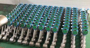
This guide provides a structured framework for deciding when a mag meter is the right choice, when it is the wrong choice, and — critically — what to use instead. Whether you are a plant engineer specifying meters for a new water-treatment facility, a process engineer evaluating flow measurement on a gas header, or a procurement professional comparing vendor quotes, the data here will prevent costly mismatches. The methodology draws on installation and application data from Jade Ant Instruments, which has deployed over 12,000 electromagnetic flow meters across water, chemical, pharmaceutical, food, and mining sectors.

1. Understanding Magnetic Meter Basics
1.1 How Magnetic Meters Operate
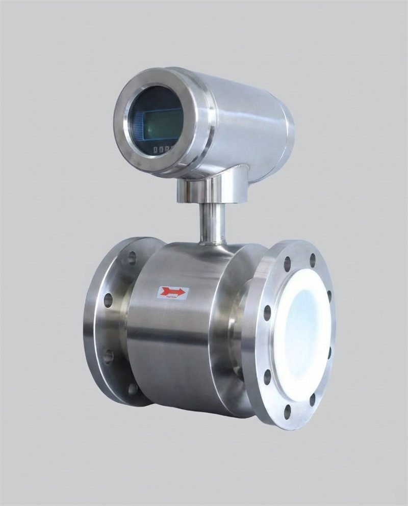
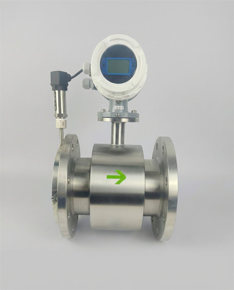
A magnetic flow meter applies Faraday’s law of electromagnetic induction: when a conductive fluid moves through a magnetic field, it generates a voltage proportional to its velocity. Two electromagnetic coils in the meter body create a magnetic field perpendicular to the flow direction. Two electrodes flush-mounted on opposite sides of the tube sense the induced voltage. Because the pipe diameter is fixed, the measured velocity converts directly to volumetric flow rate: Q = v × A, where v is the average fluid velocity and A is the cross-sectional area of the tube.
The elegance of this principle is that it involves no moving parts, no obstructions in the flow path, and zero permanent pressure drop. The measurement is independent of fluid viscosity, density, temperature, and pressure — as long as the fluid is conductive. This makes mag meters the default choice for water-based fluids, acids, bases, slurries, and any aqueous solution with electrical conductivity above the meter’s minimum threshold (typically ≥ 5 µS/cm).
1.2 Typical Measurement Principles and Outputs
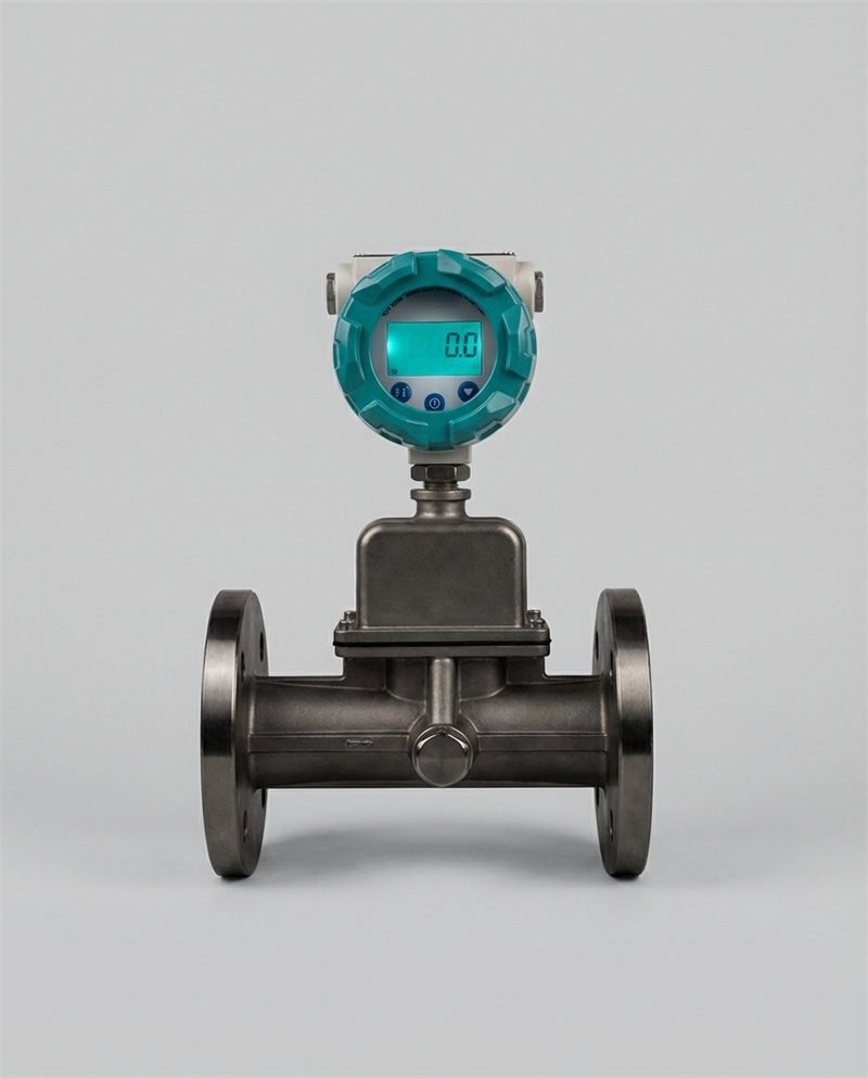
Mag meters produce a DC or pulsed-DC voltage signal at the electrodes that is proportional to flow velocity. Modern transmitters convert this signal to standard industrial outputs: 4–20 mA analog (with optional HART overlay), pulse/frequency output for totalizing, and digital fieldbus protocols (Modbus RTU/TCP, PROFIBUS PA, FOUNDATION Fieldbus). Accuracy specifications range from ±0.2 % of reading on premium custody-transfer meters to ±0.5 % on standard process meters and ±1.0–2.5 % on insertion types (Sino Insts comparison).
The transmitter also provides diagnostics: electrode coating detection, empty-pipe detection, excitation-coil integrity check, and grounding verification. These diagnostics are accessible via HART or the local display and are essential for long-term measurement integrity — Jade Ant Instruments’ datasheet guide explains how to interpret these diagnostic specifications on a vendor data sheet.
1.3 Common Configurations and Terminology
Three primary configurations exist. Inline (full-bore) meters are installed as a spool piece between pipe flanges; the measurement tube matches the pipe diameter, providing ±0.2–0.5 % accuracy with no flow disturbance. Insertion mag meters mount through a single-point probe inserted via a hot-tap fitting; they are cheaper and easier to retrofit but sacrifice accuracy (±1.0–2.5 % of full scale) because they sample flow at a single point rather than the full cross-section. Wafer (sandwich) styles are compact inline meters designed to fit between two flanges without a separate spool piece, saving space and weight.
Key terminology includes: liner (the non-conductive layer between the fluid and the meter body — typically PTFE, hard rubber, PFA, or ceramic), electrode (the sensor contact with the fluid — 316L SS, Hastelloy C, titanium, tantalum, or platinum-iridium), and empty-pipe detection (a function that flags when the pipe is not full, which would cause false readings).
2. Differences Between Liquid and Gas Applications
2.1 How Fluid State Affects Measurement Principles
The fundamental barrier is conductivity. Faraday’s law requires a conductive medium moving through the magnetic field to generate a measurable voltage. Liquids like water (conductivity ~200–800 µS/cm), wastewater (500–2,000 µS/cm), acids (1,000–100,000+ µS/cm), and milk (~4,000 µS/cm) produce robust electrode signals. Gases — air, nitrogen, natural gas, CO₂, steam — have effectively zero electrical conductivity. No conductivity means no induced voltage, which means zero measurement signal. A mag meter installed on a gas line does not read low or inaccurately; it reads nothing at all, or produces noise-driven random values.
Even within the liquid domain, some fluids are off-limits. Pure hydrocarbons (diesel, gasoline, lubricating oils) have conductivity below 0.01 µS/cm — far below the 3–5 µS/cm minimum. Deionized water at 18.2 MΩ·cm resistivity (0.055 µS/cm) is also unmeasurable by standard mag meters, though specialty capacitance-coupled designs like Yokogawa’s ADMAG CA can handle fluids down to 0.01 µS/cm.
2.2 Key Challenges Unique to Liquids vs Gases
Liquid challenges center on electrode fouling, liner compatibility, entrained air, and two-phase (liquid + gas) conditions. Electrode fouling from scale, grease, or biological growth insulates the electrode from the fluid, progressively degrading signal strength. Entrained air bubbles above ~5 % by volume cause signal noise and over-reading. Abrasive slurries (mining tailings, cement) erode liners if the wrong material is specified.
Gas challenges are simpler to state: mag meters do not work on gas. Period. The relevant challenge is ensuring that engineers and procurement teams understand this limitation before purchase — Jade Ant Instruments’ top-10 mag meter applications guide explicitly lists the technology’s fluid-compatibility boundaries to prevent mis-specification. For gas measurement, alternative technologies (thermal mass, vortex, Coriolis, ultrasonic, differential pressure) must be selected based on the gas type, temperature, pressure, and accuracy requirement.
2.3 When to Prefer One Design Over Another
Choose a mag meter when: the fluid is a conductive liquid (≥5 µS/cm), you need zero pressure drop, accuracy of ±0.2–0.5 % is required, the fluid may contain solids or be abrasive, and bi-directional measurement is needed. Choose an alternative technology when: the fluid is a gas, steam, or non-conductive liquid (hydrocarbons, solvents, DI water); when mass flow (not volumetric) is the required measurement; or when the pipe cannot be kept full (open-channel flow — though some mag meters now support partially filled pipes with specific electrode configurations).
Technology Comparison: Mag Meter vs Alternatives for Liquids and Gases
| Parameter | Magnetic (Mag) | Coriolis | Thermal Mass | Vortex | Ultrasonic |
|---|---|---|---|---|---|
| Measures Liquids? | Yes (conductive only) | Yes (any) | Limited | Yes | Yes |
| Measures Gases? | No | Yes | Yes (primary use) | Yes | Yes (inline) |
| Measures Steam? | No | Limited | No | Yes (primary use) | No |
| Min. Conductivity | ≥3–5 µS/cm | None | N/A (gas only) | None | None |
| Accuracy (liquid) | ±0.2–0.5 % | ±0.1–0.2 % | N/A | ±0.75–1.5 % | ±0.5–1.0 % |
| Accuracy (gas) | N/A | ±0.35–0.5 % | ±1–3 % | ±1.0–1.5 % | ±1.0–2.0 % |
| Pressure Drop | Zero | Moderate | Negligible | Moderate | Zero (clamp-on) |
| Moving Parts | None | None (vibrating tubes) | None | None | None |
| Handles Slurries? | Excellent | Fair | No | Poor | Poor |
| Equipment Cost (4-in) | $1,500–$6,000 | $5,000–$20,000 | $1,500–$8,000 | $1,200–$5,000 | $3,000–$12,000 |
3. Key Performance Parameters
3.1 Bandwidth, Accuracy, and Repeatability
Mag meter accuracy is typically specified as ±0.2 % to ±0.5 % of reading for inline models and ±1.0 % to ±2.5 % of full scale for insertion types. The distinction between “% of reading” and “% of full scale” matters enormously at low flows: a meter rated ±0.5 % of reading at 100 GPM still delivers ±0.5 GPM error at 10 GPM, but a meter rated ±1 % of full scale (with 200 GPM span) has ±2.0 GPM error at 10 GPM — a 20 % relative error. Always confirm the accuracy basis on the vendor datasheet.
Repeatability — the ability to reproduce the same reading under identical conditions — is typically ±0.1 % for inline mag meters, making them excellent for process control loops where consistent behavior matters more than absolute accuracy. Bandwidth (update rate) ranges from 1–25 Hz on standard process meters to 100+ Hz on specialized fast-batch or filling meters.
3.2 Response Time and Settling Behavior
Standard mag meters have response times of 0.5–5 seconds (T90), configurable via damping settings in the transmitter. For fast-batch applications — pharmaceutical filling, beverage packaging — Jade Ant Instruments’ industrial flow monitor comparison recommends meters with ≤0.1-second response and high-speed pulse output. Settling behavior after a step change is typically first-order with configurable time constants; over-damping smooths noise but introduces lag that delays control-loop response.
3.3 Pressure Drop and Flow Considerations
One of the mag meter’s strongest selling points is zero permanent pressure drop. The measurement tube has the same inside diameter as the adjacent pipe (when properly sized), so there is no restriction, no vena contracta, and no energy loss. This is a decisive advantage in systems where pump energy is expensive or where downstream pressure must be preserved — for example, gravity-fed water distribution networks or low-pressure chemical injection loops. By contrast, a vortex meter of the same size introduces 1–3 psi of ΔP at rated flow, and an orifice plate 5–10 psi.

4. Materials and Compatibility
4.1 Wetted Parts Materials and Corrosion Resistance
Three wetted components define a mag meter’s chemical compatibility: the liner, the electrodes, and the flange/body material. The table below summarizes the most common options and their application fit.
| Component | Material | Max Temp | Key Properties | Best For |
|---|---|---|---|---|
| Liner | PTFE (Teflon) | 180 °C (356 °F) | Universal chemical resistance; smooth surface resists buildup | Acids, bases, solvents, pharma, food |
| PFA | 200 °C (392 °F) | Similar to PTFE with better high-temp performance | High-temp chemicals, steam condensate | |
| Hard Rubber (Ebonite) | 80 °C (176 °F) | Excellent abrasion resistance; low cost | Abrasive slurries, mining tailings, wastewater | |
| Ceramic (Al₂O₃) | 180 °C (356 °F) | Extreme abrasion resistance; brittle to thermal shock | Mining, cement slurry, severe erosion | |
| Electrode | 316L Stainless Steel | — | General-purpose; resists mild corrosion | Water, wastewater, mild chemicals |
| Hastelloy C-276 | — | Excellent resistance to oxidizing and reducing acids | HCl, H₂SO₄, mixed acids, chlorinated solvents | |
| Titanium (Ti) | — | Outstanding resistance to chlorides and seawater | Seawater, brine, desalination, chlor-alkali | |
| Tantalum (Ta) | — | Resists virtually all acids except HF and fuming H₂SO₄ | Hot concentrated acids, pharma reactors | |
| Platinum-Iridium (Pt-Ir) | — | Universal chemical resistance; highest cost | All corrosive liquids, ultra-pure applications | |
| Body / Flange | Carbon Steel (A105) | — | Standard process; cost-effective | General water and wastewater |
| 316L Stainless Steel | — | Corrosion-resistant exterior | Chemical, pharma, food, outdoor/coastal |
4.2 Effect of Contaminants and Cleanliness Requirements
Electrode fouling is the most insidious accuracy degradation mechanism. A 0.5 mm scale layer on a 316L electrode can increase contact resistance by 300 %, attenuating the signal and causing the meter to read 3–8 % low. Modern transmitters include electrode cleaning systems — either ultrasonic (pulsed vibration to dislodge deposits) or chemical (periodic acid flush through dedicated cleaning ports). For food and pharmaceutical applications, CIP (clean-in-place) compatibility with 85 °C NaOH and HNO₃ cycles is mandatory; PFA liners and Hastelloy or tantalum electrodes are the standard materials for these services.
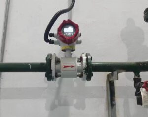
4.3 EMC/Grounding and Compatibility with Fluids
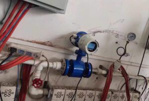
Proper grounding is the single most critical installation requirement for mag meters. The fluid must be at the same electrical potential as the meter body. On metallic pipes, flange-to-flange contact provides this ground path. On plastic, lined, or FRP pipes, grounding rings (316L or Hastelloy) must be installed between the meter flanges and the pipe flanges. Jade Ant Instruments’ installation best-practices guide reports that missing grounding on plastic pipes accounts for 23 % of all mag meter commissioning callbacks — making it the second-most-common installation error after insufficient straight-run.
5. Fluid Properties and Their Impact
5.1 Viscosity, Density, and Conductivity Implications
Unlike turbine or Coriolis meters, mag meter readings are independent of fluid viscosity and density — the induced voltage depends solely on velocity and conductivity. This makes mag meters ideal for high-viscosity fluids (syrups, polymers, slurries up to 70 % solids) that would stall a turbine rotor or overload a Coriolis tube. The only fluid property that matters is conductivity: a minimum of 3–5 µS/cm for standard four-wire excitation, or 10 µS/cm for two-wire (loop-powered) models (Azbil technical article). Common conductivity values for reference: tap water 200–800 µS/cm, process water 50–200 µS/cm, soft drinks ~1,000 µS/cm, 10 % NaOH ~200,000 µS/cm, pure hydrocarbons <0.01 µS/cm.
5.2 Temperature and Pressure Effects on Metering
Temperature primarily affects liner and electrode materials rather than the measurement principle. PTFE liners delaminate above 180 °C; PFA extends the ceiling to 200 °C; ceramic handles higher temperatures but is brittle. Pressure affects mechanical design: standard flanged mag meters handle ANSI 150 (285 psig at ambient) to ANSI 600 (1,480 psig); wafer styles are typically limited to ANSI 150. For high-pressure applications (chemical injection at 3,000+ psig), specialized high-pressure mag meter bodies or Coriolis meters may be required.
5.3 Two-Phase Flow and Slugs: How to Handle
Two-phase flow (liquid + gas bubbles) is the mag meter’s Achilles heel in liquid service. Air entrainment above ~3–5 % by volume causes electrode signal noise, erratic readings, and over-counting because bubbles increase the apparent velocity of the liquid phase. Solutions include: installing the meter in a vertical upflow orientation (bubbles rise past the electrodes), adding an upstream degassing vessel, using empty-pipe detection to mask readings during gas slugs, or selecting a meter with adaptive signal processing (e.g., Emerson’s Rosemount 8750W with advanced noise filtering). For applications where two-phase flow is inherent (some mining and chemical processes), consider alternative technologies like variable-area meters that tolerate bubbles better.
6. Installation and Piping Configurations
6.1 Inline vs Insertion Meters
Inline mag meters occupy the premium accuracy tier (±0.2–0.5 % of reading) and are specified for new installations where the pipe can be cut to insert the spool piece. Insertion mag meters sacrifice accuracy (±1.0–2.5 % of full scale) but gain installation convenience — they can be installed via hot-tap without process shutdown, cost 40–60 % less than inline equivalents, and serve pipe sizes from 4 inches to 120 inches where a full-bore meter would be prohibitively expensive. A Jade Ant Instruments water-meter selection guide recommends inline for custody transfer, billing, and process control loops; insertion for monitoring, trending, and large-pipe retrofit applications.
6.2 Straight-Run Requirements and Upstream/Downstream Devices
Mag meters require less straight-run than most other technologies because Faraday’s law integrates velocity across the entire cross-section. The industry standard is 5D upstream and 2–3D downstream from the electrode plane (Emerson installation specifications). After a partially open valve or double-elbow in different planes, increase to 10D upstream. This is a significant advantage over vortex (15–30D) or thermal (10–25D) meters and is one reason mag meters are so popular in retrofit projects with limited pipe space.
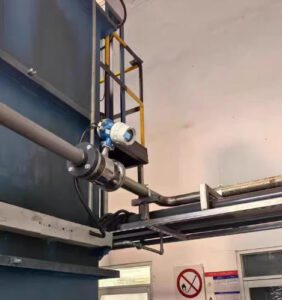
6.3 Orientation, Mounting, and Maintenance Access
For liquid service, the preferred orientation is vertical with flow upward — this ensures the pipe remains full and air bubbles rise past the electrodes rather than collecting at the top of the tube. Horizontal mounting is acceptable if the electrodes are positioned at the 3-o’clock and 9-o’clock positions (horizontal axis), never at 12 o’clock (top) where air collects or 6 o’clock (bottom) where sediment settles on the electrode face. For maintenance access, specify a transmitter that can be remote-mounted up to 30 m from the sensor body using a shielded signal cable — this allows the display and electronics to be at eye level even when the sensor is in a pit or ceiling space.
Watch: Electromagnetic Flow Meter — Working Principles Explained
This video explains how magnetic flow meters use Faraday’s law to measure conductive liquids, covers installation considerations, and demonstrates real-world mag meter assemblies.
7. Measurement Range and Turndown
7.1 Selecting the Appropriate Range for Liquids vs Gases
Inline mag meters offer turndown ratios of 100:1 or better, measuring velocities from 0.1 ft/s (0.03 m/s) to 33 ft/s (10 m/s). This wide rangeability makes them excellent for systems that modulate significantly — a municipal water distribution main that peaks at 5,000 GPM during morning demand and drops to 200 GPM overnight. The meter handles both extremes without range-switching or accuracy degradation.
For gas applications (where you cannot use a mag meter), turndown varies by technology: thermal mass meters offer 100:1–200:1 (the widest for gas), vortex meters 15:1–30:1, and DP devices 3:1–5:1. This is a crucial sizing consideration — if your gas flow modulates across a wide range, a thermal mass meter is often the only option that maintains accuracy across the full envelope.
7.2 Over-Range Protection and Safety Margins
Size the mag meter so the maximum expected flow falls at 70–80 % of the meter’s full-scale velocity. This provides headroom for surge events (water hammer, pump start-up) without saturating the transmitter output. Under-sizing — installing a 4-inch meter on a 6-inch pipe to “increase velocity and signal strength” — works for clean liquids but creates excessive pressure drop for slurries and increases erosion on the reducer cone. Over-sizing — installing a 6-inch meter on a 4-inch pipe — reduces flow velocity below the meter’s minimum threshold, causing noisy low-flow readings.
7.3 Calibration Strategies Across Different Fluids
Mag meters are typically factory-calibrated on water and the calibration transfers to other conductive liquids without adjustment — a unique advantage of the technology. The induced voltage depends on velocity and tube geometry, not fluid properties (beyond conductivity). However, for custody-transfer or high-value-fluid applications, a calibration on the actual process fluid or a fluid with matched conductivity provides an additional confidence layer. Calibration labs accredited to ISO/IEC 17025 can accommodate fluid-specific calibration runs; expect 2–4 weeks turnaround and $500–$2,000 per meter depending on size and fluid complexity.

8. Maintenance and Longevity
8.1 Calibration Intervals and Verification Methods
Mag meters are among the lowest-maintenance flow technologies because they have no moving parts and no wetted sensors that degrade mechanically. Recommended calibration intervals are 3–5 years for standard process applications and 12–24 months for custody-transfer service. Between calibrations, in-situ verification using the transmitter’s built-in coil-drive test and electrode-impedance check can confirm that the meter is performing within specification without removing it from the line. Jade Ant Instruments’ manufacturer comparison guide benchmarks verification features across major brands.
8.2 Sensor Life, Fouling, and Cleaning Practices
With proper liner and electrode selection, mag meter sensors routinely last 15–25 years in clean-water service. In fouling-prone applications (wastewater, food processing, mineral slurries), sensor life depends on cleaning discipline. Options include: built-in electrode cleaning (ultrasonic scrubbing or periodic high-current pulse to burn off scale), chemical CIP cycles compatible with the liner material, and manual inspection every 12–24 months. A large Southeast Asian palm-oil processor running PTFE-lined mag meters on crude palm oil found that monthly 15-minute CIP cycles with 2 % NaOH maintained electrode cleanliness and held accuracy within ±0.4 % for over 8 years without recalibration.
8.3 Diagnostics and Fault Codes for Quick Troubleshooting
Common fault codes and their meanings: Empty Pipe — the pipe is not full or conductivity is below minimum; check for air ingress or verify fluid conductivity. Coil Drive Error — the excitation coil circuit is open or shorted; inspect coil wiring and connectors. Electrode Coating — electrode impedance has increased beyond threshold; clean electrodes. Grounding Fault — potential difference between fluid and meter body exceeds limit; inspect grounding rings or grounding electrodes. Over-Range — flow velocity exceeds the transmitter’s configured maximum; re-range or re-size. Trending electrode impedance over weeks in the CMMS database reveals gradual fouling before accuracy degrades, enabling proactive cleaning rather than reactive troubleshooting.
9. Five-Year Maintenance Cost Comparison
5-Year Maintenance + Calibration Cost (4-in Meter, Process Liquid, USD)
Includes periodic calibration, sensor cleaning, and one parts replacement where applicable. Mag meters’ no-moving-parts design yields the lowest 5-year maintenance burden among all liquid-flow technologies.
10. Industry Standards and Certifications
10.1 Relevant Standards for Liquids and Gases
Mag meters for liquid measurement are governed by: ISO 20456 (flow measurement in closed conduits using electromagnetic flowmeters), ISO 6817 (measurement of conductive liquid flow in closed conduits — the predecessor), OIML R117 (dynamic measuring systems for liquids other than water — custody transfer), and MID (Measuring Instruments Directive, EU). For water billing, NSF/ANSI 61 certification ensures materials are safe for potable-water contact. ATEX/IECEx and FM/CSA certifications are required for hazardous-area installations (chemical plants, refineries).
10.2 Certification Impact on Safety and Reliability
Specifying a meter without the correct hazardous-area certification is not just a compliance gap — it is a safety violation that can void plant insurance. A mid-sized European chemical company was cited €45,000 in 2024 for operating uncertified flow instruments in an ATEX Zone 1 area. Always verify that the meter’s certification matches the area classification at the exact installation point, not just “in the plant generally.”
10.3 Documentation and Supplier Qualification Tips
Request the following documentation with every mag meter purchase order: factory calibration certificate (ISO/IEC 17025 accredited), material test report (MTR 3.1 for wetted parts), hazardous-area certificate (if applicable), NIST-traceable calibration uncertainty statement, and the transmitter’s SIL capability certificate if the meter feeds a safety instrumented function. Jade Ant Instruments provides a complete documentation package with every meter shipment, including QC inspection photos of liner bonding and electrode welds.
11. Magnetic Flow Meter Application Distribution by Industry
Mag Meter Installations by Industry Sector (Jade Ant Instruments 2024–2025 Data)
Chemical & Petrochemical — 22 %
Food & Beverage — 16 %
Pharmaceutical — 10 %
Mining & Minerals — 9 %
Other (HVAC, Power, Pulp & Paper) — 8 %
Source: Jade Ant Instruments sales and installation database, 2024–2025 (n = 3,420 meters). Water & wastewater remains the dominant sector, reflecting the technology’s unmatched performance on conductive aqueous fluids.
12. Decision-Making Checklist and Practical Tips
12.1 Quick-Start Decision Framework
Use this four-question filter to determine whether a mag meter is the right choice for your application:
Question 2: Is the liquid’s conductivity ≥ 5 µS/cm? → If NO (hydrocarbons, solvents, DI water) → Mag meter is not applicable. Evaluate Coriolis, ultrasonic, or turbine.
Question 3: Will the pipe remain full during measurement? → If NO (open channel, partially filled pipe) → Standard mag meter is not applicable. Evaluate a partially-filled-pipe mag meter or open-channel ultrasonic.
Question 4: Is the required accuracy ≤ ±0.5 % of reading? → If YES → Specify inline mag meter. If ±1–2.5 % is acceptable → Insertion mag meter is an option for large pipes and retrofits.
12.2 Red Flags to Watch During Vendor Evaluation
Be wary of vendors who: (1) claim their mag meter can measure “any fluid” without asking about conductivity — this suggests either ignorance or dishonesty; (2) quote a single liner/electrode material for all applications without reviewing your fluid data sheet; (3) cannot provide an ISO/IEC 17025-accredited calibration certificate; (4) specify zero straight-run requirement — while mag meters need less than most technologies, 5D/2D is still the minimum, and claims of “0D” should be verified with independent test data; (5) do not include grounding rings in the quotation for plastic-pipe installations.
12.3 Real-World Tips for Negotiating Specifications
For multi-meter projects (10+ units), negotiate: volume discount (typically 8–15 % off list), extended warranty (3 years instead of standard 1–2), factory-witnessed test (you or your representative observes the calibration run — standard for custody-transfer meters), and commissioning support (vendor engineer on-site for the first 2–3 installations). Jade Ant Instruments includes grounding rings, flange hardware, and a commissioning checklist in every mag meter quotation at no extra charge — compare this against competitors who list these as line-item add-ons totaling $200–$500 per meter.
Selecting a magnetic meter for liquid applications is a high-confidence decision when the fluid meets two non-negotiable criteria: it must be a liquid (not a gas), and it must have conductivity above 3–5 µS/cm. Within those boundaries, mag meters deliver an unmatched combination of zero pressure drop, ±0.2–0.5 % accuracy, slurry tolerance, no moving parts, and 15–25 year sensor life — which is why they dominate water, wastewater, chemical, food, and pharmaceutical flow measurement globally.
For gas applications, the selection shifts entirely to alternative technologies: thermal mass meters for wide-turndown gas flow, vortex meters for steam and compressed air, Coriolis meters for high-accuracy mass measurement of both liquids and gases, and ultrasonic meters for non-invasive measurement on large pipes. The technology-comparison table in Section 2 and the decision framework in Section 12 provide the structured approach needed to match the right technology to your specific fluid, accuracy, and installation constraints.
Align meter choice with your actual fluid properties and installation context — not with habit, brand loyalty, or the assumption that one technology fits all. And adopt a staged evaluation approach: pilot one or two meters on representative process lines, validate performance over 30–90 days, then scale to full deployment. Jade Ant Instruments supports this approach with loaner meters for pilot testing and project-scale rollouts backed by on-site commissioning engineering.
Frequently Asked Questions (FAQs)
Q1: What factors most influence meter accuracy for liquids vs gases?
For liquids measured by mag meters, accuracy is influenced by fluid conductivity (must be ≥5 µS/cm), electrode cleanliness (fouling can reduce signal by 3–8 %), proper grounding (50 % of field failures stem from grounding errors per Soaring Instrument), and full-pipe conditions (air bubbles above 3–5 % cause noise). For gases, accuracy depends on technology choice — thermal mass meters are affected by gas composition and temperature, vortex meters by minimum Reynolds number (Re >10,000), and Coriolis meters by gas density (low density = weaker signal). Matching the technology to the fluid’s physical properties is the single most important accuracy decision.
Q2: How do I choose between insertion and inline magnetic meters?
Choose inline when accuracy of ±0.2–0.5 % of reading is required (custody transfer, billing, process control), the pipe can be shut down for installation (4–8 hours), and pipe size is 24 inches or smaller (larger inline meters become very expensive). Choose insertion when ±1.0–2.5 % accuracy is acceptable (monitoring, trending), the pipe cannot be shut down (hot-tap installation), or the pipe diameter exceeds 24 inches. Insertion meters cost 40–60 % less than inline equivalents and install in 2–4 hours without process interruption. Jade Ant Instruments’ liquid measurement comparison provides a detailed cost-versus-accuracy analysis.
Q3: What maintenance practices extend meter life in challenging environments?
Three practices have the greatest impact: (1) implement a scheduled electrode-cleaning program — monthly CIP cycles for food/pharma, quarterly ultrasonic cleaning pulses for water/wastewater, semi-annual manual inspection for mining/slurry; (2) verify grounding integrity annually using a multimeter (resistance from fluid to earth should be <10 Ω); (3) trend electrode impedance in your CMMS — a 50 % increase from baseline indicates fouling before accuracy visibly degrades. These practices routinely extend mag meter sensor life to 20+ years even in aggressive services.
Q4: Can a magnetic flow meter measure any gas at all?
No. Electromagnetic flow meters require a conductive fluid to generate the induced voltage per Faraday’s law. All gases (air, nitrogen, natural gas, CO₂, steam) have effectively zero electrical conductivity and produce no measurement signal in a mag meter. For gas applications, use thermal mass meters (best turndown, direct mass flow), vortex meters (excellent for steam and compressed air), Coriolis meters (highest accuracy for gas mass flow), or ultrasonic meters (non-invasive option for large gas pipes).
Q5: What is the minimum fluid conductivity required for a mag meter?
Standard four-wire mag meters require a minimum of 3–5 µS/cm. Two-wire (loop-powered) models typically need ≥10 µS/cm due to lower excitation power. Specialty capacitance-coupled designs (e.g., Yokogawa ADMAG CA) can measure down to 0.01 µS/cm for ultra-pure water applications. If your fluid’s conductivity is unknown, have it tested before specifying a mag meter — a $50 lab test prevents a $5,000 mis-purchase.
Q6: How does electrode fouling affect mag meter readings?
Electrode fouling insulates the electrode surface from the conductive fluid, increasing contact resistance and attenuating the induced voltage signal. A 0.5 mm scale layer can reduce signal amplitude by 300 %, causing the meter to read 3–8 % low. The transmitter’s electrode-coating diagnostic detects this by monitoring electrode impedance. Cleaning restores accuracy immediately. In severe fouling environments, specify electrodes with bullet-nose geometry that protrude into the flow stream, reducing the surface area where deposits can accumulate.
Q7: Which liner material should I select for my application?
PTFE is the default for chemical, pharmaceutical, and food applications (universal chemical resistance, FDA-compliant, up to 180 °C). Hard rubber is preferred for abrasive slurries and mining tailings (superior wear resistance, up to 80 °C, lowest cost). PFA extends the temperature ceiling to 200 °C with PTFE-like chemical resistance. Ceramic (alumina) handles extreme abrasion (mining, cement) but is brittle and cannot tolerate thermal shock. Always cross-reference the liner’s chemical compatibility chart against your actual process fluid — not just the primary fluid, but also CIP chemicals, sterilization media, and upset-condition fluids.
Q8: What are the most common mag meter installation mistakes?
Based on Jade Ant Instruments’ field-service data, the top five are: (1) missing grounding rings on plastic pipes (23 % of callbacks), (2) mounting with electrodes at 12-o’clock position where air collects (18 %), (3) installing on a partially filled pipe without empty-pipe detection enabled (15 %), (4) insufficient straight-run after a control valve (12 %), and (5) wrong liner material for the process fluid (8 %). All five are preventable with a commissioning checklist reviewed before pipe cutting begins.
Q9: How long do magnetic flow meters typically last?
In clean-water service with proper installation and periodic verification, inline mag meters routinely last 15–25 years. The sensor body and electrodes are the most durable components; the transmitter electronics may need replacement or upgrade after 10–15 years as communication protocols evolve. In aggressive services (mining slurries, hot acids), sensor life depends on liner and electrode material selection — hard-rubber liners in a gold-mine tailings line may last only 3–5 years before erosion requires relining, while PTFE liners on 10 % HCl can last 10–15 years.
Q10: Where can I get expert help selecting a magnetic meter or its gas-measurement alternative?
Jade Ant Instruments offers free application consultations covering fluid compatibility, liner/electrode selection, installation layout review, and commissioning planning — for both magnetic meters and alternative technologies when the application calls for gas measurement. For additional reference, consult Emerson’s magnetic flow theory page, Engineering Toolbox’s flowmeter comparison, and KOBOLD’s magnetic meter overview.
References: LinkedIn Pulse / EMF Market Report (2025) — Electromagnetic Flowmeter Market Size; Fortune Business Insights (2026) — Flow Meter Market Report; Soaring Instrument — Causes of Errors in Magnetic Flow Meters; Emerson — Rosemount Magnetic Flow Theory & Installation Specifications; Azbil North America — Electromagnetic Flowmeter Technical Article; Sino Insts — Insertion vs Inline Electromagnetic Flow Meters; KOBOLD USA — Understanding Magnetic Flow Meters; Yokogawa — ADMAG CA Conductivity Specifications; Hach — Electromagnetic Flow Meter Technical Article; Engineering Toolbox — Comparing Flowmeters; ISO 20456 — Electromagnetic Flowmeters; OIML R117 — Dynamic Measuring Systems for Liquids; Jade Ant Instruments (2024–2026) — Installation Database, Field-Service Records, Manufacturer Comparison Guide.