
A rotameter — also known as a variable area flow meter — is one of the most widely deployed flow measurement instruments in industrial history. First patented in 1908 by Karl Küppers in Germany, the rotameter has survived over a century of technological disruption precisely because its operating principle requires no external power, no electronics, and no signal conditioning to deliver a real-time flow indication. According to Flow Research Inc., worldwide variable area flow meter revenues reached $280 million in 2019 and have continued to grow at a compound annual rate of approximately 4.1%, with the global market projected to reach $1.93 billion by 2034 (IntelMarketResearch, 2026). That sustained demand across chemical processing, water treatment, pharmaceutical manufacturing, HVAC, and laboratory settings tells a clear story: when a process engineer needs reliable, immediate visual flow indication at a measurement point that does not justify the cost and complexity of a digital transmitter, a rotameter remains the instrument of choice.
However, a rotameter only delivers accurate readings when three conditions are met simultaneously: correct installation, proper calibration, and disciplined reading technique. A field audit conducted across 42 chemical plants in Southeast Asia by an independent instrumentation consultancy found that 34% of rotameter measurement errors could be traced to installation defects (non-vertical mounting, reversed flow direction, insufficient straight-run pipe), 28% to expired or never-performed calibrations, and 22% to parallax reading errors by operators. Those are not instrument failures — they are procedural failures that this guide is designed to eliminate.
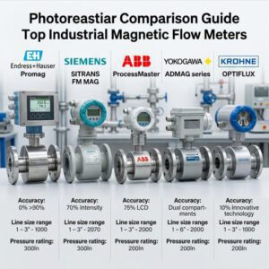
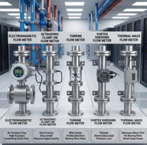
This article provides a step-by-step engineering reference for installing, calibrating, and reading a rotameter correctly — backed by real specification data, industry standards, and practical troubleshooting experience. Whether you are commissioning a new glass tube rotameter on a water treatment chemical dosing line or maintaining a metal tube rotameter in a high-pressure gas application, the procedures and principles covered here will help you extract maximum measurement value from one of the simplest instruments in your plant. For a broader comparison of rotameters against other flow measurement technologies, Jade Ant Instruments’ variable area flow meter comparison guide provides additional decision context.
What is a Rotameter?
Principle of Operation
A rotameter operates on the variable area principle: fluid enters from the bottom of a vertically mounted, upward-tapering tube and flows upward around a float (also called a plummet or indicator). As the flow rate increases, the fluid exerts greater drag and buoyancy forces on the float, pushing it higher into the tube where the annular area between the float and the tube wall is larger. The float reaches an equilibrium position where the downward gravitational force on the float exactly balances the upward forces from fluid drag and buoyancy. At that equilibrium point, the position of the float against a calibrated scale indicates the volumetric flow rate.
The governing equation can be expressed conceptually as: the volumetric flow rate is proportional to the annular area at the float position, the square root of the net downward force on the float (float weight minus buoyancy), divided by the fluid density and a discharge coefficient that depends on the float shape and Reynolds number. In practice, this means the rotameter’s scale is only accurate for the specific fluid density and viscosity at which it was calibrated — a critical point that many operators overlook, and one that we will address in detail in the calibration section.
Video: Rotameters — All you have to know! A comprehensive explanation of the variable area flow measurement principle, float behavior, and practical considerations.
Key Components: Tube, Float, Scale, and Indicators
Every rotameter consists of four fundamental components, and understanding each one’s role is essential for proper installation, reading, and maintenance.
The metering tube is a precision-manufactured tapered cone — narrower at the bottom, wider at the top. Glass tubes (typically borosilicate glass) allow direct visual observation of the float and fluid, and are commonly used for low-to-moderate pressure applications up to approximately 200 psi and temperatures up to 121°C (250°F). Metal tubes (316 stainless steel, Hastelloy, Monel, or titanium) are used when the process fluid is opaque, corrosive, or operating at pressures up to 5,000 psi and temperatures up to 420°C (788°F). In metal tube designs, the float position is transmitted magnetically to an external indicator or electronic transmitter, since the float cannot be observed directly.
The float is the moving measurement element. Floats are manufactured in various shapes — spherical (ball), cylindrical with a conical top, or guided rod configurations — and materials ranging from glass and plastic to 316SS, tantalum, and sapphire. Float material selection directly affects the meter’s sensitivity and range: a heavier float (e.g., stainless steel, density ~8,000 kg/m³) produces a wider measurement range because greater flow force is needed to lift it, while a lighter float (e.g., glass, density ~2,500 kg/m³) provides better sensitivity at low flow rates.
The scale is marked directly on or adjacent to the tube (for glass tube rotameters) or on an external dial indicator (for metal tube rotameters). Scales are calibrated in engineering units (LPM, GPM, SCFH, m³/h) for a specific reference fluid at specific temperature and pressure conditions. Using the rotameter on a different fluid without applying correction factors will produce systematic measurement errors.
Modern rotameters may also include indicators beyond the basic visual scale: magnetic followers that transmit float position to needle pointers on external dials, 4–20 mA electronic transmitters for remote monitoring, alarm switches (high/low flow), and even HART-protocol digital communication in premium metal tube models.

Choosing the Right Rotameter
Size and Flow Range Considerations
Rotameter sizing is not a casual decision. The fundamental requirement is that your normal operating flow rate should fall between 30% and 70% of the meter’s full-scale range — not at the extreme ends. A float that operates consistently below 10% of scale is in a region where accuracy degrades sharply (most rotameter accuracy specifications are stated as a percentage of full scale, so at 10% of range, a ±2% FS accuracy translates to ±20% of reading). Conversely, a float that pins at the top of the scale during normal operation provides no headroom for detecting flow surges or upsets.
Standard rotameter sizes range from approximately 1/16″ to 6″ in tube diameter, covering flow rates from as low as 0.5 mL/min (for laboratory microflow glass rotameters) to over 4,000 GPM (for large industrial metal tube rotameters). The table below summarizes typical size-to-range relationships:
| Tube Size (Nominal) | Typical Water Flow Range | Typical Air Flow Range | Common Applications |
|---|---|---|---|
| 1/8″ – 1/4″ | 0.5 mL/min – 500 mL/min | 5 mL/min – 2 LPM | Laboratory, analytical instruments, medical gas |
| 1/2″ – 3/4″ | 0.2 – 10 LPM | 1 – 50 LPM | Chemical dosing, pilot plant, purge gas |
| 1″ – 1.5″ | 5 – 100 LPM | 20 – 500 LPM | Water treatment, cooling water, HVAC |
| 2″ – 3″ | 50 – 1,000 LPM | 200 – 5,000 LPM | Process water, industrial gas lines |
| 4″ – 6″ | 500 – 15,000 LPM | 2,000 – 50,000 LPM | Large process lines, power plant cooling |
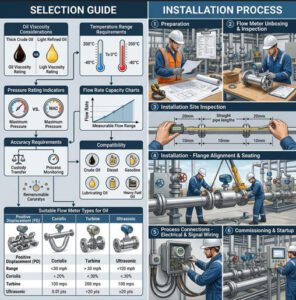
For engineering assistance matching your flow range and pipe size to the right rotameter model, Jade Ant Instruments’ flow meter selection guide provides a structured decision framework.
Material Compatibility and Environmental Factors
Material selection determines whether a rotameter survives its first week or its first decade in service. The critical wetted components — tube, float, float guide, and end fittings — must all be chemically compatible with the process fluid at actual operating temperature and pressure.
For water, mild chemicals, and non-corrosive gases, borosilicate glass tubes with 316 stainless steel fittings and floats are the standard selection. For concentrated acids (HCl, H₂SO₄, HF), PTFE-lined bodies with tantalum or Hastelloy C-276 floats are typically required. A water treatment plant in Jiangsu Province, China, reported destroying two standard 316SS rotameters within 8 months when monitoring sodium hypochlorite (NaOCl) dosing flow — the high oxidative chlorine content corroded the float guide rod, causing the float to stick. After switching to PTFE-lined rotameters with Hastelloy floats, the same application ran without incident for over 3 years.
Environmental factors beyond chemical compatibility include ambient temperature (electronics in metal tube rotameter transmitters typically operate from -40°C to +85°C, but LCD displays may fog or become unreadable below -20°C), vibration (piping vibration can cause the float to oscillate, producing jittery readings), and area classification (for hazardous areas, rotameters must carry appropriate explosion-proof or intrinsically safe certifications — ATEX, IECEx, or FM/CSA).
Installing the Rotameter

Orientation and Mounting Requirements
The single most critical installation requirement for any gravity-operated rotameter is perfectly vertical mounting with flow direction from bottom to top. This is non-negotiable. The entire measurement principle depends on the gravitational force acting on the float in exact opposition to the upward fluid forces. As Yokogawa notes in its installation guidance, the rotameter is the one flow meter type that can only be mounted vertically with bottom-to-top flow.
In practice, “perfectly vertical” means within ±1° of true vertical. Even a 3° tilt can introduce a measurement bias of 1–3% because the effective gravitational component acting on the float is reduced (cos 3° = 0.9986, but the float’s equilibrium geometry in the tapered tube amplifies this effect). Use a spirit level during installation, and verify alignment after tightening all piping connections — pipe stress from adjacent fittings can torque the meter body out of alignment after bolting.
Some spring-loaded rotameter designs allow horizontal installation, but these are specialized models that must be specifically ordered for horizontal use. Never install a standard gravity-operated rotameter horizontally — the float will rest against the tube wall and provide no meaningful indication.
Piping Connections and Installation Tips
Proper piping practice around a rotameter includes several often-overlooked requirements. Provide a minimum of 5 pipe diameters of straight, undisturbed pipe upstream of the rotameter inlet and 3 pipe diameters downstream to prevent flow profile distortion. Install isolation valves upstream and downstream to allow removal for maintenance without draining the entire line. For glass tube rotameters, use a bypass line with a bypass valve so the process can continue flowing during rotameter removal or calibration.
Thread sealant (PTFE tape or pipe dope) should be applied carefully to prevent debris from entering the tube and fouling the float. For flanged connections, use appropriate gaskets and tighten bolts in a cross-pattern to even the flange loading — uneven compression can crack glass tubes. Metal tube rotameters with process connections rated above 150# class should be torqued to manufacturer-specified values.
Install a strainer or filter upstream of the rotameter if the process fluid carries any particulates. A 60-mesh strainer is a reasonable default for most liquid applications. A water treatment chemical supplier in Gujarat, India, documented a 45% reduction in rotameter maintenance interventions after adding inline strainers ahead of their sodium hypochlorite dosing rotameters — the strainers trapped precipitated calcium and magnesium solids that had previously fouled the float mechanism every 6–8 weeks.
Common Installation Pitfalls to Avoid
The most common installation errors — based on aggregated field service data from multiple instrumentation suppliers — include: mounting the rotameter with flow direction reversed (top-to-bottom), which pins the float at the bottom and provides no reading; installing adjacent to vibrating equipment (pumps, compressors) without vibration isolation, which causes the float to oscillate 2–5% around its true position; over-tightening glass tube end connections, which induces micro-cracks that propagate under thermal cycling; failing to remove shipping restraints (many rotameters ship with a foam insert or wire clip holding the float in place — this must be removed before operation); and piping the rotameter in a dead-leg or recirculation loop where air can become trapped in the tube, causing the float to read erroneously high.
For a comprehensive guide to flow meter installation best practices — including piping diagrams, straight-run requirements, and commissioning checklists — Jade Ant Instruments maintains a detailed technical resource.
Safety Considerations
Pressure and Temperature Limits
Every rotameter has defined maximum allowable working pressure (MAWP) and maximum temperature ratings that must not be exceeded under any operating condition, including transient upset conditions. Glass tube rotameters are the most pressure-limited: typical MAWP ranges from 100 psi to 200 psi at room temperature, and this rating decreases as temperature increases. The ABB glass tube flowmeter technical guide (PDF) documents that for 1″ to 2″ glass tube meters, the maximum allowable pressure is reduced by approximately 1% per 2°C for operating temperatures above 95°C.
Metal tube rotameters operate at significantly higher pressure and temperature limits — up to 5,000 psi and 420°C (788°F) in specialized models. Yokogawa’s ROTAMETER RAKD series, for example, is rated to 160 bar (2,320 psi) and 250°C (482°F). However, these limits apply to the body and tube only — the associated electronics and transmitter have their own (typically much lower) temperature limits.
| Rotameter Type | Max Pressure (Typical) | Max Temperature (Typical) | Accuracy (Typical) | Recommended Applications |
|---|---|---|---|---|
| Glass Tube | 100–200 psi | 121°C (250°F) | ±2% of full scale | Clean liquids, laboratory, chemical dosing |
| Plastic (Acrylic/Polyamide) | 50–100 psi | 63°C (145°F) | ±3–5% of full scale | Water, mild chemicals, HVAC |
| Metal Tube (316SS) | Up to 5,000 psi | Up to 420°C (788°F) | ±1.6% of full scale | High pressure/temp, opaque fluids, hazardous areas |
| PTFE-Lined | Up to 150 psi | Up to 200°C (392°F) | ±2% of full scale | Corrosive chemicals, ultra-pure applications |
Handling and Maintenance Safety
Glass tube rotameters present a laceration and chemical exposure hazard if the tube fractures under pressure. Always install glass tube rotameters with a safety shield (most manufacturers offer them as standard or optional accessories). Before performing any maintenance on a pressurized rotameter, isolate the upstream and downstream valves, verify zero pressure on the gauge, and drain the meter. When handling glass tubes, wear cut-resistant gloves and safety glasses. For rotameters in hazardous area service (flammable gases or vapors), ensure that any electrical connections to transmitters or alarm switches comply with the area classification and that hot work permits are obtained before any welding or grinding near the instrument.
Calibrating for Accuracy
Calibration Principles and When to Calibrate
A rotameter’s factory calibration is performed under specific reference conditions: typically water at 20°C and 1 atm for liquid meters, or air at 20°C and 1.013 bar absolute for gas meters. If your process fluid differs from the reference fluid in density, viscosity, or operating pressure/temperature, the scale readings will contain a systematic bias that must be corrected through either recalibration with the actual process fluid or application of mathematical correction factors (conversion factors are available from most rotameter manufacturers based on fluid density and viscosity ratios).
Fluke’s rotameter calibration guide recommends calibrating at least annually, and more frequently (every 6 months) for rotameters in critical dosing or safety-related applications. The EPA Standard Operating Procedure for field rotameters requires annual calibration as a baseline compliance requirement. Beyond these intervals, recalibrate any time the rotameter has been disassembled, had its float replaced, been exposed to a fluid different from the calibration fluid, or shows readings that drift more than half its stated accuracy tolerance.
Step-by-Step Calibration Procedure
The following procedure applies to a typical volumetric (gravimetric or bucket-and-stopwatch) calibration against a traceable reference. This is the most widely accessible method for field calibration.
Step 1: Prepare the setup. Install the rotameter in its operating position (vertical, flow bottom-to-top). Connect the upstream supply and downstream collection or return. Ensure the reference flow measurement device (calibrated reference meter, weigh scale, or graduated collection vessel and calibrated timer) is in place and within its own calibration validity period.
Step 2: Establish stable flow at the first test point. Most calibration procedures test at 5 points across the range: 10%, 25%, 50%, 75%, and 100% of full scale. Open the control valve slowly and stabilize flow at the 10% mark. Wait at least 60 seconds for the float to stabilize completely — rushing this step is one of the most common sources of calibration scatter.
Step 3: Measure the reference flow. For the gravimetric method: divert flow into the collection vessel, start the timer simultaneously, collect for a measured time period (typically 60–120 seconds for adequate volume resolution), stop the timer, and weigh the collected fluid. Calculate the reference volumetric flow rate from mass/density/time. For the master meter method: record the reference meter reading simultaneously with the rotameter reading.
Step 4: Record and compare. Log the rotameter indication and the reference measurement. Repeat Steps 2–3 at each of the remaining test points (25%, 50%, 75%, 100%). Calculate the error at each point as (rotameter reading − reference value) / full scale × 100%.
Step 5: Adjust or document. If all errors fall within the manufacturer’s stated accuracy specification (typically ±2% of full scale for glass tube, ±1.6% for metal tube), the rotameter passes calibration. If errors exceed tolerance, some metal tube rotameters allow zero and span adjustment via potentiometer or digital parameter configuration. Glass tube rotameters generally cannot be adjusted — they must be returned to the manufacturer for refurbishment or replaced.
Verification and Traceability Considerations
For calibrations to hold up under regulatory scrutiny (FDA, EPA, ISO 9001, ISO 17025), the reference standard used to calibrate the rotameter must itself be traceable to a recognized national metrology institute (NIST in the US, PTB in Germany, NIM in China). NIST’s metrological traceability policy defines this as “an unbroken chain of calibrations, each contributing to the measurement uncertainty.” In practice, this means your reference weigh scale needs a current NIST-traceable calibration certificate, your timer needs to be verified against a traceable frequency source, and the density value you use to convert mass to volume must come from a recognized reference (e.g., IAPWS-IF97 for water density as a function of temperature).
Document every calibration with a formal record that includes: instrument tag number and serial number, calibration date, reference standard(s) used (with certificate numbers), test points and measured errors, pass/fail determination, name of the calibrating technician, and next calibration due date. This record is your evidence during audits.
Reading the Flow Rate Correctly
Interpreting the Scale and Float Position
Where you read the float position relative to the scale is the single largest source of operator-induced measurement error. The reading point depends on the float shape, and getting this wrong produces errors of 3–10% even on a perfectly calibrated meter.
For a spherical (ball) float, read the scale at the center (equator) of the ball — the widest point. For a cylindrical float with a conical top, read at the top edge of the widest cylindrical section, not the tip of the cone. For a plumb-bob or teardrop float, read at the top edge of the float (the sharp upper edge). As KOBOLD USA explains, “rotameters are read at the top of the float against the scale on the flow body” — but “top” means the reading edge appropriate to the float geometry, which the manufacturer’s manual will specify.
To eliminate parallax error, position your line of sight so that your eyes are at exactly the same height as the float reading edge, and look straight at the scale — not from above, below, or the side. If you are reading from above, you will read low; from below, you will read high. This parallax bias is particularly significant for glass tube rotameters where the curved tube surface acts as a lens. An operator reading a 100 mm scale from 30° below eye level can introduce a 5–8 mm apparent displacement — equivalent to 5–8% of full-scale flow error.
Reading at Different Orientations and Conditions
If the rotameter is installed at a height that makes eye-level reading impractical (e.g., mounted 3 meters above the floor in overhead piping), consider installing a mirror-assisted reading aid, a metal tube rotameter with a remote-readable indicator dial, or — for critical measurement points — a metal tube rotameter with 4–20 mA output connected to a local display or control room monitor. For Jade Ant Instruments rotameter models equipped with electronic transmitters, the signal can be routed to a PLC or SCADA system, eliminating the need for field reading entirely.
Environmental conditions also affect reading reliability. Strong backlighting or direct sunlight can create glare on glass tubes, making the float difficult to distinguish. Condensation on the exterior of a glass tube (common when measuring cold fluids in humid environments) obscures the float entirely. For these conditions, a metal tube rotameter with magnetic indication is the more robust choice.
Common Troubleshooting
Symptoms and Likely Causes
Effective troubleshooting starts with recognizing which symptom pattern points to which root cause. The table below maps the most frequently reported rotameter problems to their most probable causes, based on aggregated field service reports from multiple instrumentation service providers:
| Symptom | Most Likely Cause(s) | Corrective Action |
|---|---|---|
| Float stuck at bottom (no movement despite flow) | Shipping restraint not removed; float jammed by debris; float/guide rod corrosion causing binding | Remove restraint; flush with clean solvent; disassemble and inspect float and guide rod concentricity |
| Float oscillates / reading fluctuates ±5–15% | Pulsating flow (pump pulsation); piping vibration; entrained air/gas bubbles in liquid; two-phase flow | Install pulsation dampener or back-pressure valve; add pipe supports; install upstream deaerator |
| Float stuck at top of scale (pegged high) | Flow rate exceeds meter range; float material density too low for fluid; reversed installation (flow pushing float up against top stop) | Verify flow rate against meter range; check float material; verify flow direction arrow on body |
| Reading higher than actual flow | Fluid density lower than calibration fluid; fluid temperature higher than calibration temperature; air trapped in tube | Apply density/temperature correction factor; bleed air from tube; recalibrate with actual fluid |
| Reading lower than actual flow | Fluid density higher than calibration fluid; scaling or deposits narrowing the tube annulus; worn or damaged float | Apply correction factor; clean tube and float; inspect float for chips or erosion and replace if damaged |
| No float visible (glass tube) | Float sunk to very bottom; float broken into fragments; tube clouded by chemical attack or scaling | Check for float fragments; inspect tube clarity; replace tube if etched or opaque |
Troubleshooting Flow Inconsistencies
When the rotameter reading does not match an independent reference measurement (a master meter, a bucket-and-stopwatch test, or a mass balance calculation), systematically check these factors in order: (1) Is the rotameter installed truly vertical? Re-verify with a spirit level. (2) Is the float moving freely? Gently tap the tube — the float should bob slightly and return to its equilibrium position. If it sticks, the meter needs cleaning or the float/guide assembly needs inspection. (3) Is the meter reading being taken at the correct point on the float? Review the manufacturer’s reading instructions for your specific float geometry. (4) Has the calibration been performed with a fluid that matches the current process conditions? If the fluid has changed (different concentration, temperature, or composition), recalibration or correction is required. (5) Are there upstream flow disturbances (partially open valve, elbow, pump) within 5 pipe diameters of the inlet? Flow profile distortions affect reading accuracy.
Maintenance and Longevity
Routine Cleaning and Inspection
Establish a preventive maintenance schedule based on the service environment. For clean fluid applications (potable water, clean gas), a semi-annual visual inspection and annual cleaning is typically sufficient. For dirty or scaling fluids (wastewater, chemical dosing lines, cooling water with mineral content), quarterly cleaning and inspection is a more realistic interval. Industry maintenance guidance consistently recommends using only manufacturer-approved cleaning solutions — harsh chemicals or abrasive tools can scratch glass tubes (introducing micro-fracture points) or corrode float surfaces (altering the float weight and invalidating calibration).
During each inspection, check for: tube clarity (for glass — is the scale still legible? Are there etch marks or clouding?), float condition (chips, erosion, discoloration, freedom of movement), end fitting seal integrity (leaking O-rings, degraded gaskets), and for metal tube rotameters, transmitter function (verify that the 4–20 mA output tracks the indicator needle position across the range).
Wear Parts and Replacement Intervals
Rotameters have very few wear parts — which is one of their longevity advantages. The primary replacement items are O-ring seals (replace annually or whenever the meter is disassembled), the float (replace when visibly eroded, chipped, or corroded — in clean water service, floats can last 10+ years; in abrasive slurry dosing, they may need replacement every 2–3 years), and the glass tube (replace if cracked, chipped, etched, or if the scale markings have become illegible). Metal tube rotameters may additionally require replacement of the magnetic coupling (follower magnet) if the indicator needle becomes sluggish or stops tracking the float — typically after 15–20 years of service. According to Kytola Instruments, industrial flow meters generally last 10–20 years, with rotameters at the longer end of that range due to their mechanical simplicity.
Root Causes of Rotameter Field Failures
Based on aggregated field service data from chemical processing and water treatment applications:
Distribution of Rotameter Field Failure Causes
Fouling / deposits: 22%
Calibration drift/expired: 16%
Material incompatibility: 12%
Mechanical damage: 10%
Other: 6%
Applications and Best Practices

Industry Examples and Best-Fit Scenarios
Rotameters serve a remarkably wide range of industries, though their role is typically as a local flow indicator or simple flow controller rather than a high-accuracy custody transfer device. The most prevalent application sectors and their specific use cases include:
Water and wastewater treatment: Rotameters monitor chemical dosing flows (chlorine, sodium hypochlorite, polymer, coagulant) where real-time visual confirmation of dosing rate is operationally critical. A municipal water treatment plant in Zhejiang Province operates 24 glass tube rotameters on its chemical dosing manifold, with each meter providing the operator instant visual confirmation that the dosing pump is delivering the expected flow rate — a capability that digital meters with remote transmitters also provide, but at 3–5× the installed cost per point.
Chemical processing: Purge gas metering, catalyst injection monitoring, and cooling water flow verification are all classic rotameter applications. In these roles, the rotameter’s zero-power-required operation is a genuine advantage — if the plant loses instrument air or electrical power, the rotameter continues to indicate flow.
Pharmaceutical and laboratory: Rotameters provide immediate visual flow verification for gas chromatography carrier gas, fermentation air supply, and clean utility distribution. The simplicity of a rotameter — no electronics, no software, no firmware updates — aligns well with the pharmaceutical industry’s preference for validated-and-unchanging measurement systems.
HVAC and building services: Balancing valves integrated with rotameter-type flow indicators are standard components in hydronic HVAC systems, allowing technicians to visually verify flow rates during commissioning and periodic balancing checks.
Rotameter Deployment by Industry Sector (%)
Best Practices for Repeatable Measurements
Consistent, repeatable measurements from a rotameter require disciplined operating procedures. Always read the float at the same reference point on the float geometry (widest diameter for ball floats, top edge for guided floats) and at eye level. Allow at least 30 seconds for the float to stabilize after any flow change before taking a reading. Never slam open or close isolation valves upstream of a rotameter — rapid pressure changes can damage the float or crack glass tubes. Record the process fluid temperature at the time of each reading if the fluid temperature varies more than ±5°C from the calibration reference temperature, and apply the appropriate correction factor to the reading.
Documentation and Record-Keeping
For rotameters in regulated applications (pharmaceutical GMP, EPA compliance, ISO 9001/14001 quality systems), maintain a documented instrument register that includes: instrument tag number and location, manufacturer, model, serial number, fluid specification, flow range, calibration due date, and maintenance history. Each calibration event should generate a calibration certificate or as-found/as-left data record. Each maintenance event should be logged with the date, actions performed, parts replaced, and the technician’s name. These records transform a simple mechanical flow indicator into a traceable measurement instrument that can withstand regulatory audit.
Installing, calibrating, and reading a rotameter correctly is not complicated — but it demands attention to a specific set of non-negotiable procedures. Vertical mounting within ±1° of true plumb, bottom-to-top flow direction, upstream strainer protection, and vibration isolation form the installation foundation. Annual calibration against a traceable reference standard, with formal documentation of test points, errors, and pass/fail determinations, ensures the meter’s readings remain within tolerance throughout the calibration interval. And disciplined reading technique — correct float reference point, eye-level alignment, adequate stabilization time — eliminates the operator-induced errors that field audits consistently identify as the most common source of rotameter inaccuracy.
The cumulative impact of getting these procedures right is substantial. A correctly installed, calibrated, and read rotameter delivering ±2% FS accuracy on a chemical dosing line means the process stays within its design envelope, chemical consumption remains predictable, and treatment quality is maintained. The same rotameter — installed at a 3° tilt, reading from 30° below eye level, operating on a fluid 15°C above the calibration temperature with no correction applied — could easily show a combined error of 10–15%, turning a reliable indicator into a misleading one.
Whether you are specifying new rotameters for a greenfield project or improving the measurement reliability of existing installations, the principles in this guide apply universally across glass tube, metal tube, and plastic rotameter designs. For engineers who need application-specific selection assistance, Jade Ant Instruments provides engineering consultation and a comprehensive range of rotameter and liquid flow measurement solutions — including glass tube, metal tube, and electronically-equipped variable area flow meters — backed by factory-direct technical support and rapid configuration turnaround.
Frequently Asked Questions (FAQs)
1. What is the basic principle of a rotameter?
A rotameter operates on the variable area principle. Fluid flows upward through a vertically mounted tapered tube, lifting a float to a height where the upward fluid forces (drag and buoyancy) balance the downward gravitational force on the float. The float position against a calibrated scale directly indicates the volumetric flow rate. No external power is required. The measurement depends on the equilibrium between fluid dynamics and gravity, which is why the rotameter must always be mounted vertically with flow direction from bottom to top. For a deeper explanation with visual diagrams, DwyerOmega’s variable area flow meter resource provides comprehensive technical detail.
2. How often should a rotameter be calibrated?
For general industrial service, annual calibration is the industry-standard minimum interval. Critical dosing applications (pharmaceutical, water treatment disinfection, safety-related gas detection) should be calibrated every 6 months. The EPA’s Standard Operating Procedure for field rotameters mandates annual calibration as a compliance baseline. Beyond scheduled intervals, recalibrate whenever the rotameter has been disassembled, repaired, exposed to a different fluid, or shows readings that drift beyond half its stated accuracy tolerance. Always calibrate using a traceable reference standard and document the results formally.
3. How do I know if a rotameter is the right size for my system?
The cardinal rule of rotameter sizing is that your normal operating flow rate should fall between 30% and 70% of the meter’s full-scale range. Operating below 10% of scale degrades accuracy dramatically (a ±2% FS specification becomes ±20% of reading at 10% of scale). Operating above 90% leaves no headroom for detecting flow surges or upsets. To size correctly, document your minimum, normal, and maximum expected flow rates, then select a meter whose full-scale range accommodates your maximum flow while keeping normal operation in the 30–70% sweet spot. Jade Ant Instruments’ selection guide can help you match flow parameters to the right meter size.
4. What maintenance tasks are essential for rotameters?
Essential maintenance includes: periodic cleaning of the tube interior and float surface to remove deposits, scaling, or biological growth (quarterly for dirty fluids, semi-annually for clean fluids); visual inspection of the glass tube for cracks, chips, or etching; verification that the float moves freely through its full range; O-ring and gasket replacement at least annually or whenever the meter is disassembled; upstream strainer cleaning to prevent particulate bypass into the meter; and scheduled calibration verification. Metal tube rotameters with electronic transmitters additionally require verification that the 4–20 mA output signal tracks correctly across the indication range.
5. Can a rotameter be used for both liquids and gases?
Yes, but a rotameter calibrated for liquid cannot be used directly for gas measurement (or vice versa) without recalibration or mathematical correction. The float equilibrium position depends on fluid density and viscosity, which differ by orders of magnitude between liquids and gases. Many rotameter manufacturers offer dual-scale models with one scale calibrated for water and another for air on the same tube, but these scales are only accurate at the specific reference conditions (temperature, pressure) printed on the nameplate. For gas applications at pressures significantly different from atmospheric, a pressure correction factor must be applied to convert the indicated flow to actual flow.
6. Why does my rotameter float oscillate instead of reading steadily?
Float oscillation (±5–15% fluctuation around the mean reading) is almost always caused by pulsating flow, entrained gas bubbles in liquid, or piping vibration. Reciprocating pumps and diaphragm pumps generate pulsating flow that causes the float to bounce in rhythm with the pump strokes. Solutions include installing a pulsation dampener or surge tank upstream of the rotameter, adding a downstream back-pressure valve to stabilize the flow, or relocating the rotameter further from the pulsation source. If the cause is piping vibration from nearby rotating equipment, adding pipe supports and vibration isolation mounts typically resolves the issue.
7. What is the difference between a glass tube and a metal tube rotameter?
Glass tube rotameters allow direct visual observation of the float and fluid, are lower in cost, and are suitable for clean, non-corrosive fluids at pressures up to approximately 200 psi and temperatures up to 121°C. Metal tube rotameters handle opaque, corrosive, or high-pressure/high-temperature fluids (up to 5,000 psi and 420°C), use magnetic coupling to transmit the float position to an external indicator, and can include electronic transmitters for remote monitoring. Metal tube models cost 3–10× more than comparable glass tube versions, so the selection should be driven by process requirements rather than preference.
8. How do I correct rotameter readings when the process fluid differs from the calibration fluid?
When the process fluid has a different density or viscosity than the calibration reference fluid, a correction factor must be applied to convert the indicated reading to the actual flow rate. For liquids, the correction factor is approximately the square root of (calibration fluid density − float density) / (process fluid density − float density). For gases at pressures other than the calibration pressure, the correction involves the square root of the ratio of actual gas density to calibration gas density. Most rotameter manufacturers publish correction factor tables and calculation tools. Alternatively, you can request a rotameter with a custom scale calibrated specifically for your process fluid and operating conditions.
9. Can rotameters provide electronic output signals for remote monitoring?
Metal tube rotameters — and some premium glass tube models with magnetic followers — can output 4–20 mA analog signals, pulse outputs, and in some cases HART digital communication for integration into PLCs, SCADA systems, and DCS platforms. These electronically-equipped rotameters bridge the gap between the simplicity of a variable area meter and the data integration capabilities of fully electronic flow meters. Jade Ant Instruments’ flow monitor comparison discusses how different meter types integrate with modern industrial automation systems.
10. What is the typical accuracy of a rotameter, and how does it compare to other flow meter types?
Glass tube rotameters typically achieve ±2% of full scale; high-quality metal tube rotameters reach ±1.6% of full scale. By comparison, electromagnetic flow meters achieve ±0.2–0.5% of reading, Coriolis meters reach ±0.1% of reading, and turbine meters achieve ±0.5–1% of reading. The critical distinction is “of full scale” vs. “of reading”: at 50% of a rotameter’s scale, ±2% FS equates to ±4% of the actual reading; at 10% of scale, it equates to ±20% of reading. For applications where ±2–5% accuracy is adequate and the operational benefits of simplicity, zero power, and instant visual indication outweigh the need for higher precision, the rotameter remains the optimal choice.

Whether you are installing your first rotameter or standardizing measurement practices across an entire plant, proper procedure is the foundation of reliable flow data. For personalized engineering support and a complete range of flow measurement solutions — from rotameters to electromagnetic and vortex meters — contact Jade Ant Instruments for a rapid technical consultation.