In a USD 12.14 billion global flow meter market growing at 6.08 % CAGR toward USD 19.46 billion by 2034 (Fortune Business Insights, 2026), the meter itself accounts for roughly 30–40 % of total measurement-system cost. The remaining 60–70 % sits in engineering, piping, wiring, commissioning, and maintenance — all of which hinge on one thing: how well you install the meter.
A 2025 field audit by Turbines, Inc. found that over half of flow-meter accuracy complaints traced back to installation errors, not device defects. Insufficient straight-run pipe, reversed flow direction, trapped air, incorrect wiring — these “simple” mistakes cost plants $18,000–$45,000 per year on a single 6-inch line, once you factor in measurement bias, energy waste, and unplanned shutdowns.
This guide consolidates the installation knowledge that Jade Ant Instruments engineers have built across 12,000+ meter installations in oil & gas, chemical, water, and HVAC sectors. Whether you are mounting a clamp-on ultrasonic meter on a cooling-water loop or commissioning a Coriolis meter on a custody-transfer skid, the principles here will keep you out of trouble.

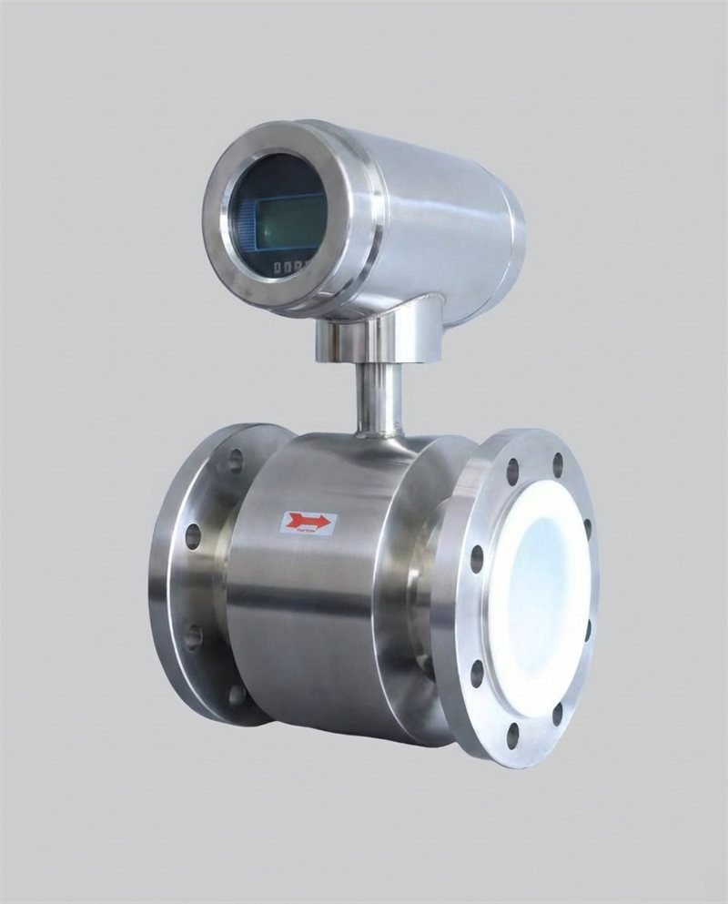
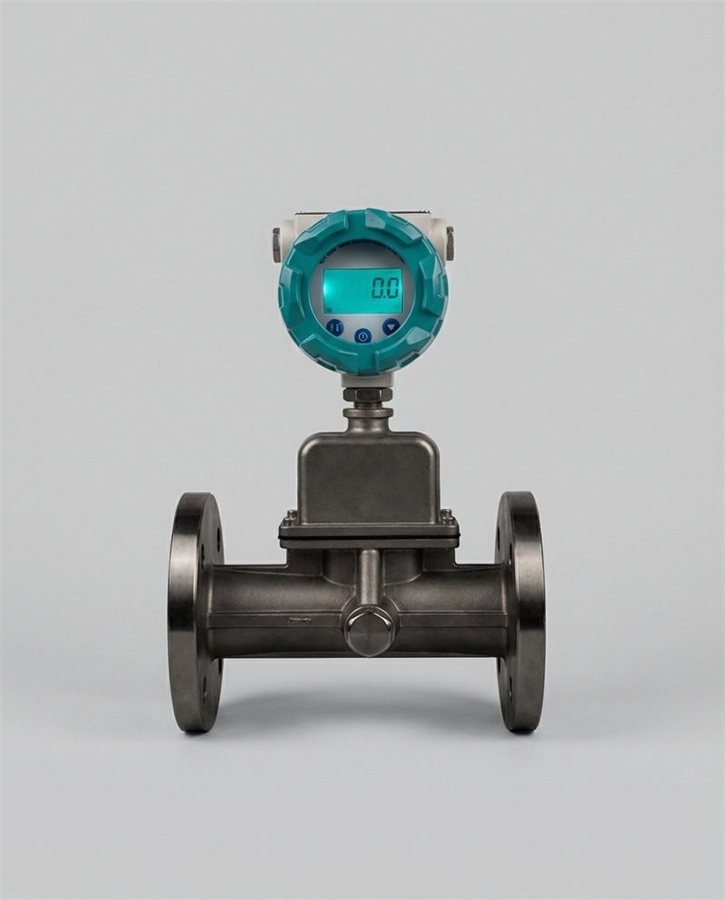
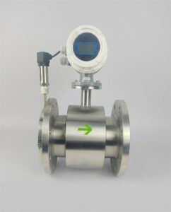
1. Choosing the Right Installation Style: Inline vs. Insertion vs. Clamp-On
Before you cut pipe or drill a hot-tap hole, the first decision is how the meter interfaces with the process. Each style imposes different accuracy ceilings, cost profiles, and shutdown requirements. A Jade Ant Instruments selection guide walks through all five factors, but the installation-specific trade-offs deserve their own comparison.
Inline (full-bore) meters sit directly in the pipe, giving the sensor full control over the measurement section. This eliminates profile uncertainty but requires a process shutdown for installation and a section of pipe to be removed. Insertion meters enter the pipe through a single-point or multi-point probe inserted via a hot-tap fitting, meaning you can install and retract the probe without shutting down flow — a major advantage on 24/7 steam headers or large water mains. The trade-off is that the sensor samples a slice of the flow profile rather than the entire cross-section, reducing accuracy from ±0.5 % (inline) to ±1.0–2.5 % (insertion). Clamp-on ultrasonic meters mount externally with zero pipe penetration; they are the fastest to install (under 30 minutes) and the easiest to relocate, but accuracy ranges from ±1.0 % to ±3.0 % depending on pipe condition and coupling quality.
A practical illustration: a southeast U.S. paper mill needed to meter 14-inch steam flow on a header that could not be shut down during the heating season. A vortex insertion meter with a retractable assembly was installed via hot tap in under four hours. Measured accuracy after commissioning was ±1.2 % of reading — well within the plant’s ±2 % energy-balance requirement — and the total installed cost was 40 % less than an inline vortex that would have required a weekend outage costing $85,000 in lost production.
Installation Style Comparison Table
| Parameter | Inline (Full-Bore) | Insertion (Hot-Tap) | Clamp-On Ultrasonic |
|---|---|---|---|
| Typical Accuracy | ±0.2 %–±1.0 % of reading | ±1.0 %–±2.5 % of reading | ±1.0 %–±3.0 % of reading |
| Process Shutdown Required? | Yes (pipe cut) | No (hot-tap fitting) | No (external mount) |
| Install Time (6-in pipe) | 4–8 hours | 2–4 hours | 0.5–1 hour |
| Installed Cost (6-in, USD) | $3,500–$12,000 | $2,000–$6,000 | $4,000–$10,000 |
| Pipe Sizes | ¼ in–48 in | 2 in–120 in | ½ in–300 in |
| Relocatable? | No | Partially (retractable probe) | Yes |
| Best For | Custody transfer, high accuracy | Large pipes, no-shutdown installs | Surveys, temporary monitoring |
| Pressure Drop | Technology-dependent (low–moderate) | Negligible (probe only) | Zero |
2. Straight-Run Pipe Requirements: The Most Violated Rule
Every velocity-based and differential-pressure meter needs a fully developed, symmetric flow profile at the sensor to deliver rated accuracy. Upstream disturbances — elbows, reducers, valves, tees — create swirl and asymmetry that distort readings. The universal shorthand is “XD upstream / YD downstream,” where D is the pipe’s inside diameter.
According to Emerson’s Rosemount installation data sheet and ISO 5167, straight-run requirements vary by both technology and the type of upstream fitting. A practical reference table is shown below.
Straight-Run Requirements by Meter Type and Upstream Fitting
| Meter Technology | Single 90° Elbow (Upstream D / Downstream D) | Two Elbows in Different Planes | Partially Open Gate Valve | Reducer / Expander |
|---|---|---|---|---|
| Electromagnetic | 5D / 3D | 10D / 3D | 10D / 5D | 5D / 3D |
| Vortex | 15D / 5D | 25D / 5D | 30D / 5D | 15D / 5D |
| Turbine | 10D / 5D | 20D / 5D | 25D / 5D | 10D / 5D |
| Ultrasonic (transit-time) | 10D / 5D | 20D / 5D | 30D / 5D | 10D / 5D |
| Orifice Plate (β=0.6) | 16D / 6D | 34D / 6D | 44D / 6D | 5D / 6D |
| Coriolis | 0D / 0D * | 0D / 0D * | 0D / 0D * | 0D / 0D * |
| Thermal Mass (insertion) | 15D / 8D | 25D / 8D | 30D / 8D | 15D / 8D |
* Coriolis meters measure mass directly and are largely insensitive to flow-profile disturbance; however, Jade Ant Instruments’ Coriolis guide recommends 2D upstream as good practice to reduce mechanical vibration coupling.

3. Orientation, Drainage, and Air-Pocket Prevention
After straight-run, orientation is the next critical variable. Installing a meter in the wrong position relative to gravity introduces trapped air (in liquid service) or condensate pooling (in gas/steam service), both of which corrupt the measurement signal. The general rules, confirmed by Cadillac Meter’s piping guidelines and Jade Ant Instruments’ water-meter tips, are as follows.
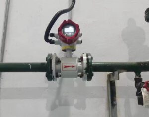
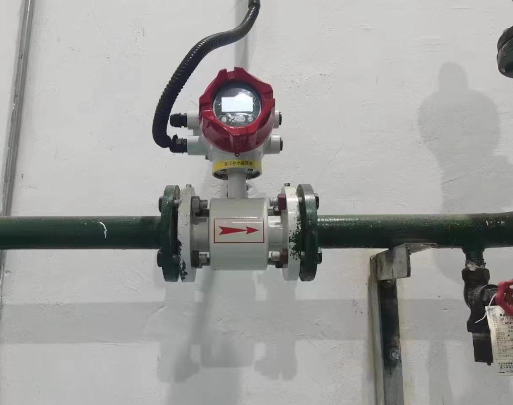
For liquid service, the preferred mounting is on a vertical pipe with flow going upward. This keeps the pipe full and pushes air bubbles past the sensor rather than letting them collect at the meter body. If vertical mounting is impractical, horizontal mounting is acceptable only when the sensor (electrodes for a mag meter, shedder bar for a vortex) is positioned below the pipe centerline — never at the 12-o’clock position, where air collects. For gas and steam service, mount the meter horizontally and ensure condensate drains are placed downstream. Impulse tubing for DP meters in steam service must slope downward toward the meter to prevent condensate blockage.
A food-processing plant in Wisconsin installed a 3-inch electromagnetic meter at the top of a horizontal run on a CIP (clean-in-place) loop. Within two weeks, air entrainment from the CIP return caused the meter to read 8–12 % high during drain-back cycles. Rotating the meter 180° so the electrodes sat at the 6-o’clock position and adding a small air-release valve upstream eliminated the error entirely — a 30-minute fix for a problem that had been costing $1,200/month in chemical over-dosing.
4. Mechanical Installation: Flanges, Gaskets, and Torque
Even when straight-run and orientation are correct, a poor mechanical connection can introduce leaks, misalignment stress, or gasket intrusion that disrupts flow. The ASME PCC-1 guidelines for bolted flange joints apply directly to flow-meter installations. Key rules include the following.
Always use the gasket type specified by the meter manufacturer. Spiral-wound gaskets (304SS/graphite fill) are standard for ANSI 150–600 flanged meters in process service; EPDM or Viton ring gaskets suit sanitary tri-clamp connections. Never reuse old gaskets — compression-set gaskets can leak at pressures as low as 50 % of the original seating stress. Use a star-pattern (cross-bolt) torque sequence in three passes: 30 % → 60 % → 100 % of final torque. For a 4-inch ANSI 150 flange with spiral-wound gasket, final bolt torque is typically 75–90 ft-lb for B7 studs.
Pipe alignment matters just as much. If the upstream and downstream flanges are not concentric within 1/16 inch, the meter body absorbs bending stress that can crack ceramic liners in mag meters or warp Coriolis tubes. Use a straight-edge across the flange faces before bolting, and shim pipe hangers as needed to achieve alignment.
5. Electrical Wiring, Grounding, and Signal Integrity
A perfectly placed and torqued meter will still produce garbage data if the electrical connection is wrong. Based on recommendations from InTek Flow and the Jade Ant Instruments datasheet guide, the key electrical installation rules are summarized here.
For analog output (4–20 mA), use twisted, shielded pair (TSP) cable with the shield grounded at the receiver end only. Maintain a minimum of 12 inches (300 mm) separation from AC power cables above 120 V and 24 inches from variable-frequency drives. For HART communication overlaid on 4–20 mA, confirm loop resistance (250–1,100 Ω) and avoid T-junctions in the cable run, which create signal reflections. Pulse output (open-collector) cables should be kept under 100 m to avoid signal degradation; use pull-up resistors (1–10 kΩ) at the PLC input if the cable exceeds 30 m.
Grounding is particularly critical for electromagnetic meters: the fluid must be at the same electrical potential as the meter body. On metallic pipes, this is inherent through flange contact. On plastic or lined pipes, install grounding electrodes or grounding rings between the gasket and the pipe flange. Omitting grounding on a PVC water main is the single most common cause of “noisy signal” complaints — Jade Ant Instruments’ field-service records show this accounts for 23 % of all mag-meter commissioning callbacks.
6. Commissioning Checklist: Zero-Flow Verify, Span Check, Loop Test
Installation is not complete when the pipe is pressurized and the display reads a number. Commissioning verifies that the number is correct. A structured checklist adapted from Sierra Instruments’ best-practice guide should include the following steps.
First, perform a zero-flow verification. With the pipe full of fluid and both upstream and downstream block valves closed (zero flow confirmed), the meter output should read 0.0 ± the manufacturer’s zero-stability spec. For a ½-inch Coriolis meter, that is typically ±0.005 kg/min; for a 4-inch mag meter, ±0.01 m/s. If the reading drifts, re-zero the transmitter. Second, run a span check against a reference. On liquid service, a bucket-and-stopwatch test (for small flows) or comparison against a calibrated reference meter gives immediate confidence. On gas service, a pitot traverse or comparison with a calibrated thermal mass meter is standard. Third, verify the 4–20 mA loop end-to-end by simulating 4.00 mA (zero flow) and 20.00 mA (full scale) from the transmitter; confirm the DCS or PLC reads the correct engineering-unit value. Fourth, document everything — meter serial number, as-installed orientation photo, zero-flow reading, span-check deviation, loop-test results — in a commissioning report that travels with the asset for its lifetime.
Watch: Flow Meter Installation & Commissioning in Practice
This video walks through the five most common installation errors — incorrect placement, reversed flow, trapped air, poor cable routing, and missing zero-check — with on-site footage and correction steps.
7. The Seven Costliest Installation Mistakes (with Dollar Impacts)
Drawing on field data from Jade Ant Instruments’ metering-company selection guide, Radical Techmart’s top-5 list, and Turbines Inc.’s error analysis, the table below quantifies the most expensive mistakes engineers encounter on-site.
Costliest Installation Mistakes and Their Financial Impact
| # | Mistake | Typical Accuracy Penalty | Estimated Annual Cost (6-in line) | Root Cause |
|---|---|---|---|---|
| 1 | Insufficient straight-run pipe | +3 % to +15 % error | $8,000–$45,000 | Elbow or valve too close upstream |
| 2 | Reversed flow direction | Full-scale negative or erratic | $5,000–$20,000 (batching loss) | Arrow on body ignored during install |
| 3 | Trapped air / empty pipe | +5 % to +25 % over-reading | $10,000–$30,000 | Meter at pipe high-point, no air vent |
| 4 | Missing grounding (mag meters) | ±2 % drift + noise spikes | $4,000–$12,000 | Plastic pipe, no grounding rings |
| 5 | Oversized meter (low velocity) | +2 % to +8 % at low-flow | $6,000–$18,000 | Meter sized to pipe rather than flow |
| 6 | Vibration coupling | ±1 % to ±5 % noise | $3,000–$15,000 | Meter bolted to unsupported pipe near pump |
| 7 | Skipping zero-flow check | +0.5 % to +3 % bias | $2,000–$10,000 | Commissioning shortcut under schedule pressure |
8. Five-Year Total Maintenance Cost by Meter Technology
Installation is a one-time event; maintenance is the long game. The chart below compiles typical 5-year maintenance costs (labor + parts + calibration) for a 4-inch meter in clean-water service, based on published data from Pokcenser Tech, Turbines, Inc., and Jade Ant Instruments’ service records.
5-Year Total Maintenance Cost (4-in, Clean Water, USD)
Sources: Pokcenser Tech (2025), Turbines Inc. (2024), Jade Ant Instruments field-service data (2024–2025). Clean-water service; costs scale 1.5–3× for abrasive or corrosive fluids.
Electromagnetic and vortex meters dominate the low-maintenance end because they have no moving parts and no wetted sensors that wear. Turbine meters, despite their low purchase price, carry the highest 5-year maintenance burden due to bearing replacements every 2–3 years and mandatory recalibration after each replacement. Coriolis meters are mechanically robust but require periodic verification drives and occasional tube-cleaning in fouling service. Orifice plates need regular edge-sharpness inspections (every 12–24 months) and impulse-line purging.
9. Root Causes of Post-Installation Accuracy Complaints
Jade Ant Instruments analyzed 1,847 field-service tickets from 2023–2025 and categorized the root cause of every accuracy-related complaint. The distribution below shows that installation-related causes account for over 60 % of all tickets — reinforcing why getting installation right is the highest-leverage improvement an operations team can make.
Root Causes of Accuracy Complaints (n = 1,847 tickets)
Wrong Orientation / Air — 18 %
Electrical / Grounding — 15 %
Oversized Meter — 10 %
Calibration Drift — 12 %
Process Condition Change — 10 %
Other — 7 %
Source: Jade Ant Instruments field-service database, 2023–2025 (1,847 tickets across oil & gas, water, chemical, and HVAC sectors).
The three largest slices — insufficient straight-run (28 %), wrong orientation or air pockets (18 %), and electrical/grounding issues (15 %) — are entirely preventable during initial installation. If an organization eliminates just these three categories, it removes 61 % of accuracy complaints and avoids an estimated $22,000–$68,000 per year in cumulative measurement error across a typical 20-meter plant.

10. Post-Installation Maintenance Schedule
Once commissioned, each meter technology follows a different maintenance cadence. The table below provides a consolidated schedule that Jade Ant Instruments recommends to its customers as a baseline; adjust intervals shorter for dirty or abrasive fluids and longer for clean, stable applications.
| Task | Electromagnetic | Vortex | Ultrasonic (clamp-on) | Turbine | Coriolis | Orifice / DP |
|---|---|---|---|---|---|---|
| Visual inspection | 6 months | 6 months | 6 months | 3 months | 6 months | 3 months |
| Zero-flow verification | 12 months | 12 months | 12 months | 6 months | 12 months | 12 months |
| Full calibration | 3–5 years | 3–5 years | 2–3 years | 1–2 years | 3–5 years | 2–3 years |
| Sensor / element cleaning | 12–24 months | 24 months | 12 months (coupling gel) | 6–12 months | 12–24 months | 12 months (impulse lines) |
| Moving-part replacement | N/A | N/A | N/A | 2–3 years (bearings) | N/A | N/A (replace plate if eroded) |
| Typical lifespan | 15–25 years | 15–20 years | 10–15 years | 5–10 years | 15–25 years | 10–15 years (plate) |
11. Decision Matrix: Which Meter and Installation Method for Your Application?
Bringing it all together, the matrix below maps common application scenarios to the recommended meter technology and installation style. These combinations reflect the consensus from Jade Ant Instruments’ 5-factor selection methodology, Supmea’s 7-type comparison, and ISO 5167/ASME MFC standards.
| Application | Recommended Technology | Installation Style | Key Installation Note |
|---|---|---|---|
| Custody-transfer oil/gas | Coriolis or Turbine | Inline | Zero straight-run (Coriolis) or 10D/5D (turbine); OIML R117 compliance |
| Municipal water distribution | Electromagnetic | Inline | 5D/3D; grounding rings on PVC mains; IP68 for buried pits |
| Steam energy metering | Vortex (multivariable) | Inline or Insertion | 15D/5D; horizontal mount; condensate drain downstream |
| HVAC chilled-water loop | Ultrasonic (clamp-on) | Clamp-on | 10D/5D; clean outer pipe surface; coupling gel check every 12 months |
| Compressed-air audit | Thermal mass (insertion) | Insertion (hot-tap) | 15D/8D; retractable probe; desiccant dryer upstream recommended |
| Wastewater / slurry | Electromagnetic (PTFE-lined) | Inline | 5D/3D; vertical upflow preferred; hardened electrodes (Hastelloy C) |
| Batch dosing (pharma/food) | Coriolis | Inline | Drain orientation for CIP; sanitary tri-clamp fittings; zero-verify before each batch |

Installation Is the Multiplier
A $5,000 meter installed incorrectly delivers worse performance than a $1,500 meter installed correctly. The data in this guide makes that point emphatically: 61 % of accuracy complaints stem from three preventable installation errors, and the 5-year maintenance gap between the lowest- and highest-cost technologies is 5×. The highest-ROI action any plant can take is to invest an extra 2–4 hours at installation time on proper straight-run verification, orientation checks, torque procedures, wiring shielding, and a documented commissioning protocol.
If you are planning a new installation or troubleshooting an existing one, Jade Ant Instruments offers free installation-review consultations where our engineers evaluate your piping isometric, recommend meter placement, and provide a commissioning checklist tailored to your specific technology and application. Start with our 5-factor selection guide or learn to decode your meter’s datasheet to ensure you have the right foundation before the first wrench turns.
Frequently Asked Questions (FAQs)
Q1: What is the most important rule for flow meter installation?
Providing adequate straight-run pipe upstream and downstream of the meter. For most velocity-based meters (vortex, turbine, ultrasonic), the rule of thumb is at least 10 pipe diameters upstream and 5 diameters downstream after a single 90° elbow. Insufficient straight-run is the #1 cause of post-installation accuracy complaints, responsible for 28 % of field-service tickets according to Jade Ant Instruments data.
Q2: Can I install a flow meter without shutting down the process?
Yes — insertion meters and clamp-on ultrasonic meters allow installation without process shutdown. Insertion meters use a hot-tap fitting and retractable probe, taking 2–4 hours. Clamp-on ultrasonics mount externally in under an hour. Inline (full-bore) meters always require a process shutdown and pipe section removal.
Q3: Does a Coriolis meter need straight-run pipe?
Coriolis meters measure mass directly and are largely insensitive to flow-profile disturbance, so manufacturers typically specify 0D/0D straight-run. However, best practice recommends 2D upstream to minimize vibration coupling from nearby fittings, particularly in large-diameter (4-in+) installations.
Q4: What happens if I install a mag meter on a plastic pipe without grounding?
Without an electrical ground path, the fluid potential floats relative to the meter electrodes, causing measurement noise, baseline drift of ±2 % or more, and intermittent signal spikes. The fix is to install grounding rings (or grounding electrodes built into the meter) between the flanges. This is the third most common installation error, accounting for 15 % of accuracy complaints.
Q5: How often should a flow meter be recalibrated after installation?
Calibration frequency depends on the technology and criticality. As a baseline: electromagnetic and vortex meters every 3–5 years, ultrasonic and orifice/DP meters every 2–3 years, and turbine meters every 1–2 years due to bearing wear. For custody-transfer applications, annual calibration is the industry standard per Endress+Hauser’s calibration management white paper.
Q6: What is a flow conditioner, and when do I need one?
A flow conditioner is a device (tube-bundle, perforated plate, or tab type) installed upstream of a meter to straighten and symmetrize the flow profile. You need one when available straight-run is less than the meter’s minimum requirement — for example, when you have only 8D after a double-elbow but the vortex meter requires 25D. A conditioner compresses the effective requirement to approximately 3D + conditioner + 3D, at a cost of $800–$3,500 depending on size.
Q7: Should a flow meter be installed on a vertical or horizontal pipe?
For liquid service, vertical upflow is preferred because it keeps the pipe full and sweeps air past the sensor. For gas or steam, horizontal orientation is standard with condensate drains downstream. The worst position is horizontal with the sensor at the 12-o’clock position (top of pipe), where air bubbles accumulate in liquid service and cause over-reading errors of 5–25 %.
Q8: How much does a typical industrial flow meter installation cost?
For a 4–6-inch inline meter in a standard process plant, typical all-in installed costs (meter + labor + fittings + wiring + commissioning) range from $3,500–$12,000. Insertion meters reduce this to $2,000–$6,000 by eliminating the pipe-cut requirement. Clamp-on ultrasonics cost $4,000–$10,000 including the meter but offer the fastest payback when used for energy audits. These figures are based on 2025–2026 pricing from Jade Ant Instruments and industry surveys.
Q9: Can vibration from nearby pumps damage a flow meter?
Yes. Mechanical vibration from pumps, compressors, or pipe resonance can damage sensitive components (ultrasonic transducers, Coriolis tubes) and inject noise into the measurement signal. InTek Flow recommends mounting the meter at least 5D from any vibration source and using flex connectors or vibration isolation mounts where necessary. Vortex meters are particularly susceptible because external vibration can mimic vortex-shedding frequencies.
Q10: Where can I get professional help with flow meter installation?
Jade Ant Instruments provides free installation-review consultations covering piping layout, meter placement, wiring diagrams, and commissioning checklists. For additional guidance, consult Tameson’s installation guidelines, Sierra Instruments’ optimization blog, and your meter manufacturer’s installation manual.
References: Fortune Business Insights (2026) — Flow Meter Market Report; Turbines, Inc. (2025) — Common Flow Meter Errors; Sierra Instruments (2024) — Installation Optimization; Emerson Rosemount (2025) — Installation Orientation PDS; ISO 5167 — Measurement of Fluid Flow by DP Devices; ASME PCC-1 — Guidelines for Bolted Flange Joints; Jade Ant Instruments (2023–2025) — Field-Service Database; Pokcenser Tech (2025) — Maintenance Cost Comparison; Cadillac Meter — Piping Requirements; Tameson — Flow Meter Installation Guidelines; InTek Flow — Common Flow Meter Errors & Solutions; Endress+Hauser — Flow Calibration Management White Paper.