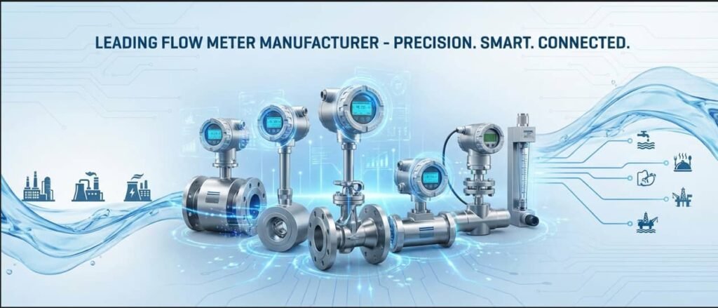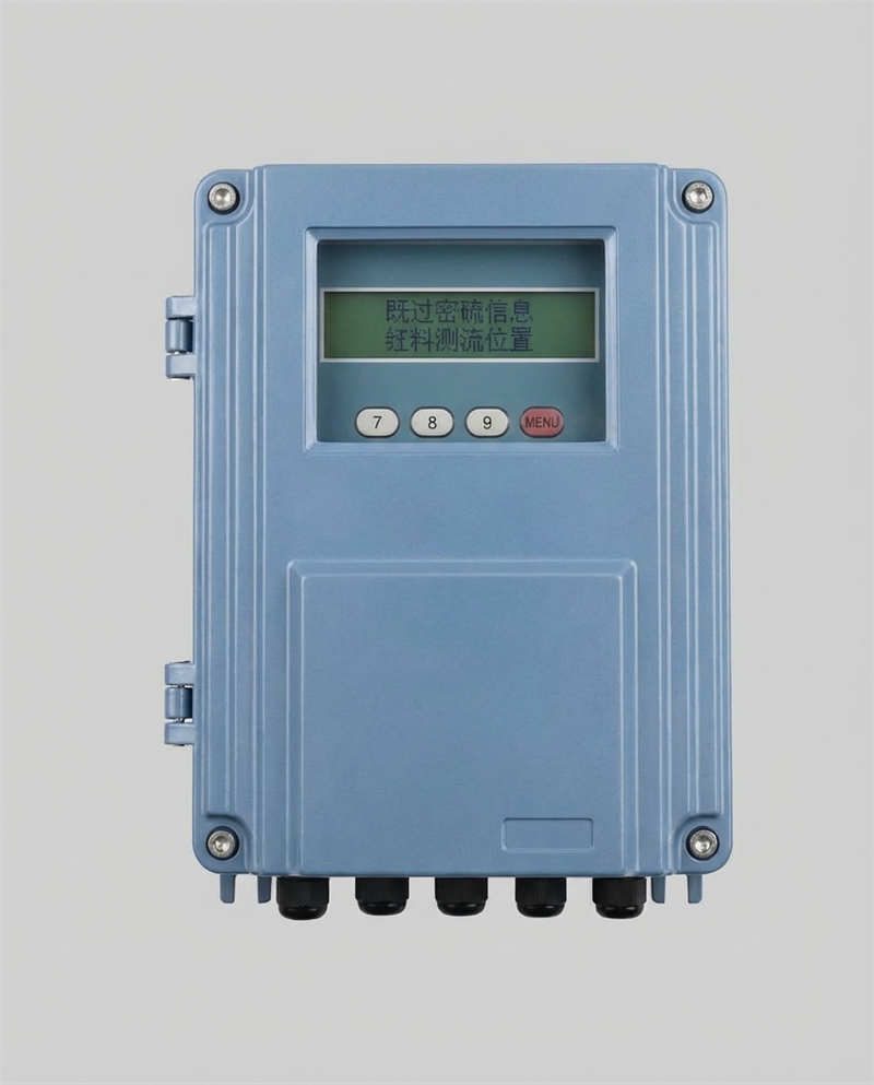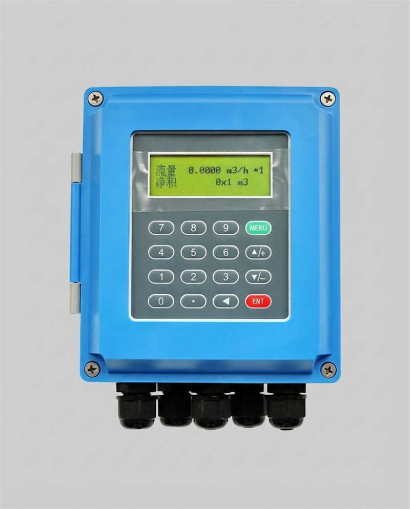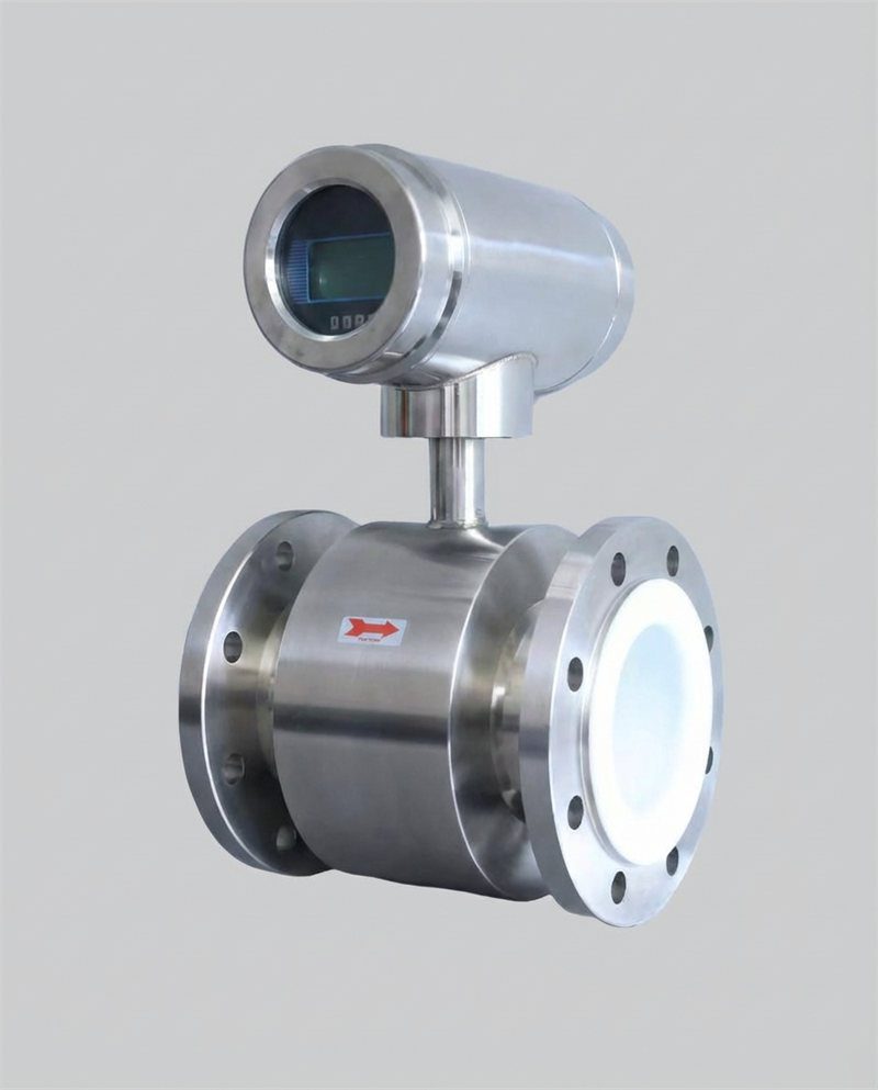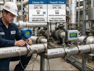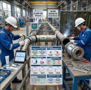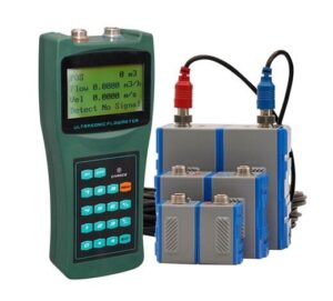
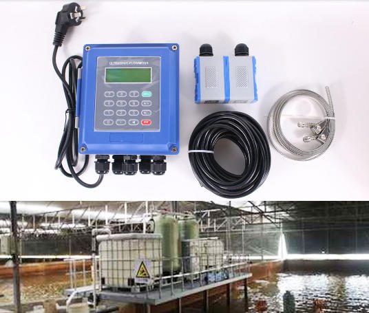
A clamp-on sensor costs about the same as a mid-range inline meter. It costs far less to install, because nobody cuts the pipe. The gap between a good reading and a bad one is rarely the electronics. It is almost always the pipe data typed into the transmitter, the place the transducers sit, and the way the cable runs back to the panel.
I. Why the Sensor You Choose Decides the Reading
A clamp-on ultrasonic flow sensor is a pair of transducers that clamp to the outside of a pipe. Each one sends a sound pulse through the wall and the liquid. The meter times both directions. The difference becomes flow velocity, and velocity times pipe area becomes flow rate. You can read the physics in more detail in this explanation of how transit-time meters measure flow.
Nothing touches the liquid. That is why the technology gets used in retrofit work, in municipal networks, and on skids that cannot be shut down for a cut-in.
The weak point is not the electronics. In our commissioning work, four faults cause most of the accuracy complaints: a wrong wall thickness entry, a short straight run, a dry coupling face, and air in the liquid. Each one costs more than the sensor.
Here is the money version. A 1% error on a DN200 line moving 150 m³/h for 6,000 hours a year misplaces about 9,000 m³ of water. At 1.20 USD per m³, that is close to 10,800 USD a year. (Illustrative example.) Nothing broke. The installation was simply wrong.
This guide walks through ten checks. It is written for the people who sign the purchase order. That includes OEM equipment and skid-mount manufacturers, instrument distributors and importers, EPC and system integrators, industrial MRO buyers, and municipal utility teams.
II. Pipe Conditions and Material Compatibility
The pipe decides how much sound gets through. Wall thickness and material set the frequency you need. A thick wall eats high-frequency signal, so you drop to a lower frequency and a bigger crystal.
Quick definition: transducer frequency — how many times per second the crystal vibrates. Lower frequency travels further through thick or rough walls. Higher frequency gives a tighter beam and better resolution on small pipes.
| Pipe material | Typical wall | Frequency band | What to check first |
|---|---|---|---|
| Carbon steel | 4–12 mm | 1–2 MHz | Scale inside, paint and rust outside |
| Stainless steel | 2–8 mm | 2–5 MHz | Polished surface needs a good couplant film |
| PVC | 3–10 mm | 1–2 MHz | Temperature limit of the pipe, not the sensor |
| HDPE | 5–25 mm | 1 MHz | Sound speed near 2,400 m/s, so the beam bends |
| Ductile iron with cement liner | 8–20 mm | 1 MHz | The liner scatters the signal before it reaches water |
Wall thickness is the number most often entered wrong. A schedule change moves the inside diameter, and the meter trusts what you type. A DN100 pipe is 102 mm inside on schedule 40 and 97 mm on schedule 80. That is a 10% area difference, so the flow reading is 10% out before the first litre moves. No clamp-on ultrasonic flow sensor can correct that after the fact. The meter only measures what the pipe data tells it to expect.
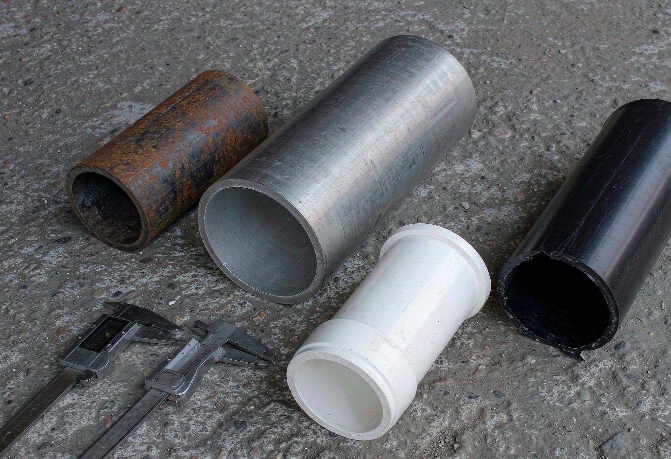
Surface condition matters as much as the metal. Loose scale, thick epoxy, and badly pitted steel all weaken the signal. Clean back to bare metal in a patch slightly larger than the transducer face. A rough cast-iron surface usually needs a low-frequency pair and a stiff couplant.
Geometry sets the rest. Very small lines below DN15 are hard to clamp accurately because the beam has little room to cross. Very large lines above DN600 need more acoustic power and often a Z-mount. Tees, reducers and elbows close to the sensor spoil the flow profile, which is the next check.
Sensors are built in families for this reason. The clamp-on ultrasonic flow meter range covers small-bore stainless lines through to large concrete-lined mains. Jade Ant Instruments gives each size pair its own spacing table.
III. Application Requirements and Fluid Behavior
Selection starts with the liquid, not the pipe. Transit-time measurement needs a liquid that carries sound and stays reasonably free of bubbles. Dirty water is fine. Foam and entrained air are not.
Three fluid properties change the answer:
- Sound speed. The meter needs it to convert time into velocity. Most units correct for temperature, but the correction assumes you picked the right liquid from the menu.
- Viscosity. It does not change sound speed much. It changes the flow profile, because a thick liquid moves in a flatter, slower shape near the wall.
- Solids and gas. Fine solids scatter a little sound and are usually tolerated. Gas bubbles block it.
You can estimate the profile with the Reynolds number calculator from Pipe Flow before you size anything. Below a Reynolds number of about 2,000 the flow is laminar and the profile is a clean parabola. Above 4,000 it is turbulent and flatter, which is easier for a single-path meter.
Quick definition: straight run — the length of straight pipe you need before and after the sensor, counted in pipe diameters (D). Fittings create swirl, and the sensor needs distance to let that swirl settle.
The common minimum is 10D upstream and 5D downstream. Go to 20D and 10D when two elbows sit close together, or when the meter feeds a billing record. A short run does not fail loudly. It biases the reading by a few percent that nobody notices until a balance sheet disagrees with a meter.
Two meters on the same line often disagree by a few percent. This flow profile error case study shows how much of that gap comes from installation rather than hardware.
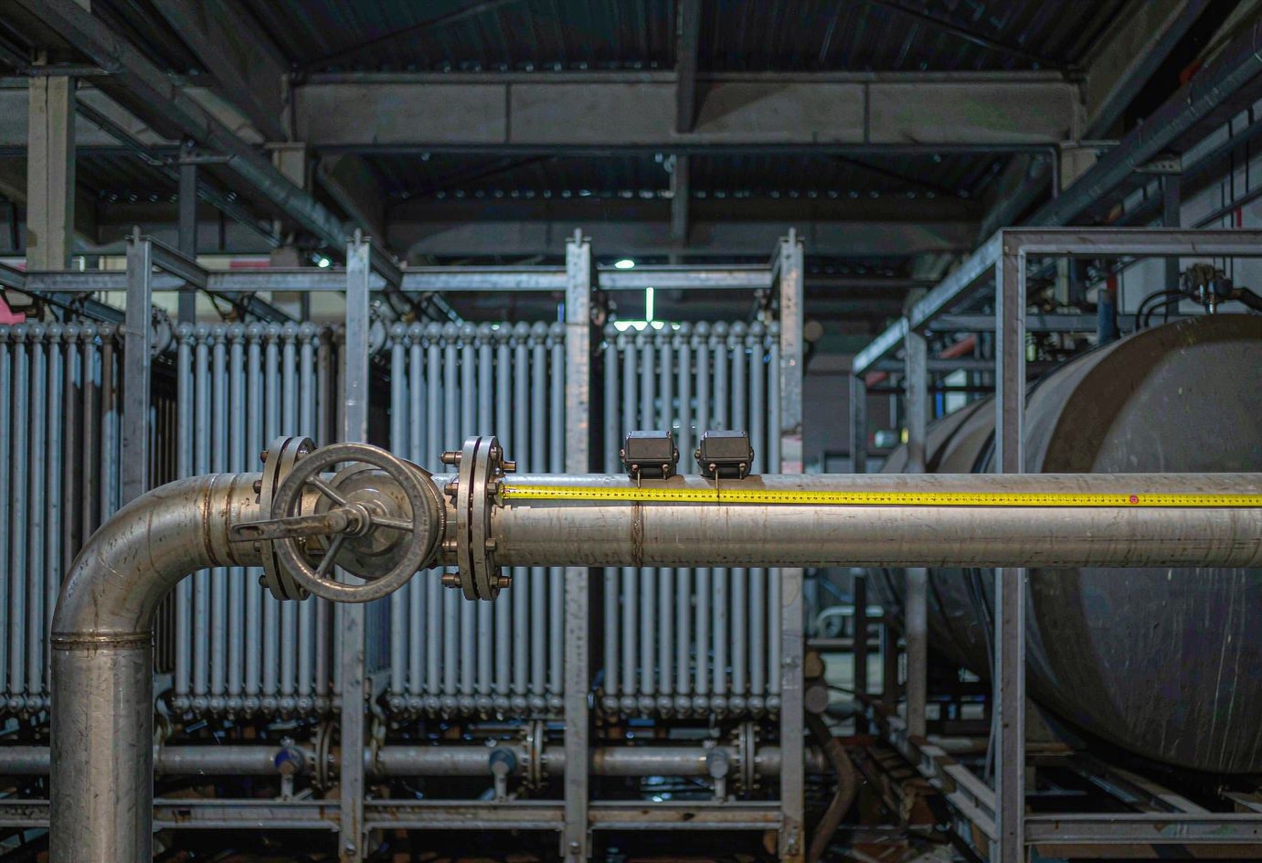
Temperature and pressure come next. Check the continuous rating, not the peak. A sensor rated to 120 °C that sits at 110 °C every day will drift as the crystal ages. Check the couplant too, because the grease is usually the first part to fail.
IV. Accuracy: What a Clamp-On Ultrasonic Flow Sensor Really Delivers
Datasheets quote nominal accuracy under laboratory conditions. Field accuracy is a different number, and buyers mix the two.
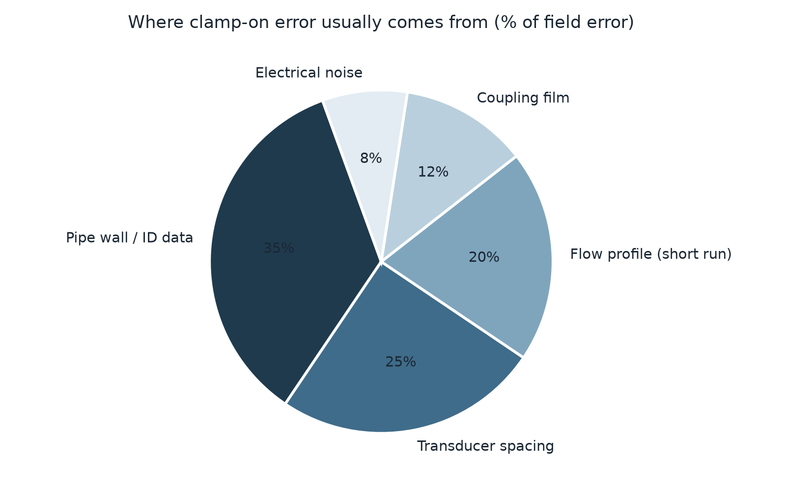
Most clamp-on meters are quoted at ±0.5% of reading, or ±1% for the economy class. In the field, expect ±1% to ±2% of reading on a clean, well-installed line. Add 1% for a short straight run. Add more if the pipe data is off.
The gap has a shape. This breakdown comes from our own service records and is illustrative, but the order rarely changes:
Quick definition: turndown — the range between the lowest and highest flow the meter can read inside its accuracy band. A 100:1 turndown means a meter good to 1 m/s still holds accuracy at 0.01 m/s.
Response time matters as much as accuracy. A meter averaging over 10 seconds reads a steady process well and misses a 3-second batch. Set the damping to the process, not to the display. If the reading needs to be smooth for a control loop, damp it in the PLC, not in the sensor.
Calibration is the last piece. A factory calibration certificate should state the method and the reference. Theoretical calibration, where the meter is checked against calculated pipe geometry, is acceptable for utility work. Wet calibration, where it is compared against a gravimetric or volumetric master, is what custody transfer and EPC handover usually ask for. Either way, ask whether the chain is traceable, and what NIST calibration services mean for the certificate you receive.
V. Installation Layout and Signal Quality
A correct installation is the only thing that turns a datasheet number into a real reading. Three details decide it: spacing, coupling, and clamping.
Transducer spacing comes from the pipe outside diameter, wall thickness, material, liquid sound speed and mounting mode. Every meter ships with a table or a menu that calculates it. Do not round the number. On a DN100 steel pipe, a 2 mm spacing error shifts the beam enough to cut signal amplitude by a third.
Mounting mode changes with pipe size. V-mount, with both transducers on the same side, works on lines up to about DN400 and gives a stronger signal on thin walls. Z-mount, with the transducers facing each other across the pipe, is the choice for large lines, thick walls and lined pipe. W-mount adds a second bounce for very small pipes.
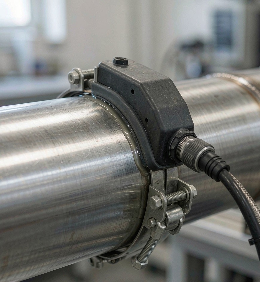
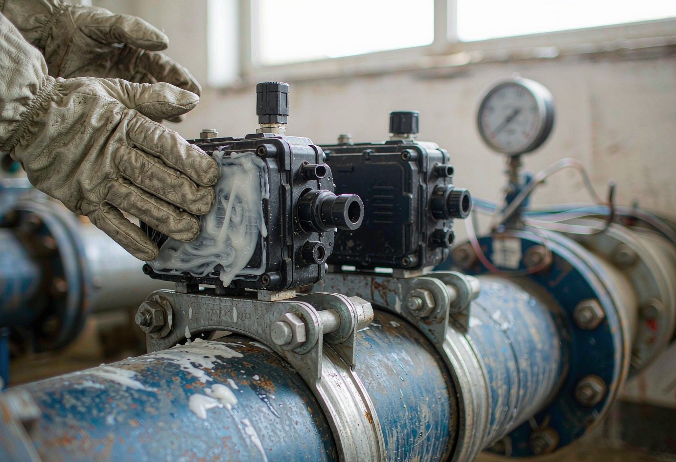
Couplant is the thin layer that carries sound from the crystal into the metal. Air gaps stop the signal, and a 0.1 mm air pocket is enough. Silicone grease covers most water lines from −40 °C to 200 °C. Above that, use a high-temperature paste, and expect to renew it more often. On vertical pipes, tape the transducer so gravity does not win.
Clamps matter more than buyers expect. A nylon strap holds a sensor in place. A steel clamp holds it in place for years. Vibration loosens straps, and a sensor that moves 0.5 mm loses gain without any alarm.
Field staff at Jade Ant Instruments walk integrators through this step on video calls during first commissioning, because spacing and coupling are where most first-time installs go wrong. The USBR Water Measurement Manual is also worth keeping on the shelf for site selection rules on large water lines.
This short demonstration shows the sequence in practice: transducers on the pipe, spacing entered, signal checked before the reading is trusted.
https://www.youtube.com/watch?v=-XMxapbQEwE
VI. Signal Integrity and Interference
An ultrasonic signal is small. A variable frequency drive (VFD) next to the cable is not. Most “bad sensor” calls we see end with a cable routed through the same tray as a motor feed.
Quick definition: VFD — a variable frequency drive, the box that changes motor speed by switching power on and off thousands of times a second. It is an efficient motor control and a loud electrical noise source.
Four habits prevent most of it:
- Route the transducer cable at least 300 mm away from motor and VFD cables.
- Cross power cables at 90° when you cannot avoid them.
- Bond the cable shield at the transmitter end only, unless the manual says both.
- Keep surplus cable short. A coiled 20 m tail next to a drive acts as an antenna.
Then read the diagnostics. Every meter reports gain and signal quality, sometimes called AGC and SNR. Gain in the 40–60 dB range with a stable quality figure above 60% is healthy. Gain climbing over weeks means the couplant is drying or the pipe surface is lifting. Gain pinned at maximum means no signal at all, and no amount of menu work will fix it.
If the plant is dense with drives and welding sets, start with hardware built for it. These EMI-resistant flow meter options compare shielding, filtering and cable practice across common models.
VII. Integration with Control Systems
OEMs and EPCs care about one thing after accuracy: does the data arrive where the control system expects it. Pick the output before you pick the meter, not after.
| Output | Best for | Watch-out |
|---|---|---|
| 4–20 mA | Legacy PLCs, simple trending | One value per loop; scaling errors are common |
| Modbus RTU | Skids, local panels, low cost | Needs correct baud, parity and termination |
| Modbus TCP | Plant networks, SCADA historians | Network segmentation and IP planning |
| HART | Retrofits into existing 4–20 mA loops | Slow for fast process data |
| Profibus PA | Large process plants with existing segments | Segment design and power budget |
Power choice follows the same logic. Loop-powered units suit skids with limited panel space. Externally powered units suit installations with displays, data logging and high-power transducers. If the skid travels, decide now whether the transmitter sits on the skid or in the plant cabinet.
Wiring standards are worth reading once. The ISA instrumentation standards cover signal levels, grounding and loop practice that most EPC specifications reference by number.
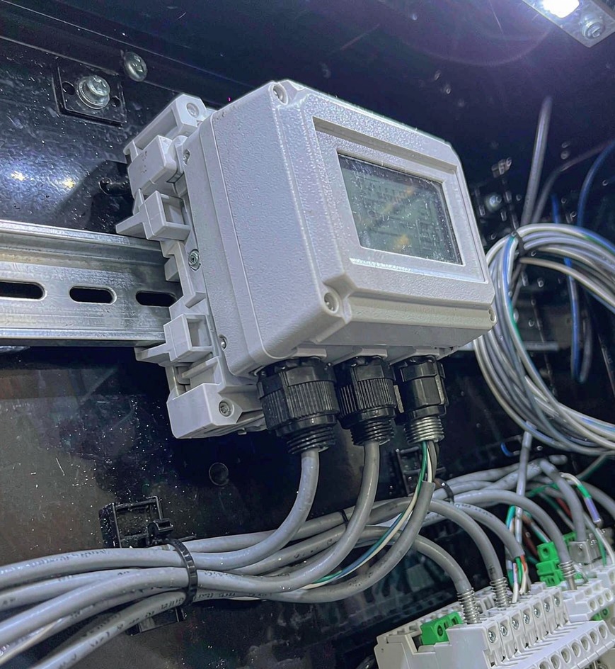
Skid builders have an extra constraint: the meter must survive transport and still pass a factory acceptance test. This skid-mounted flow meter selection guide covers mounting, tagging and pre-shipment verification for that case.
VIII. Total Cost of Ownership and Lifecycle
Purchase price is the smallest part of the bill on most projects. Installation and downtime are the rest.
The chart below compares a clamp-on set with a cut-in inline meter on a DN200 water line. The numbers are illustrative, built from typical Middle East and Southeast Asia project costs. The pattern holds in most markets: the inline meter is cheaper to buy and far more expensive to install.
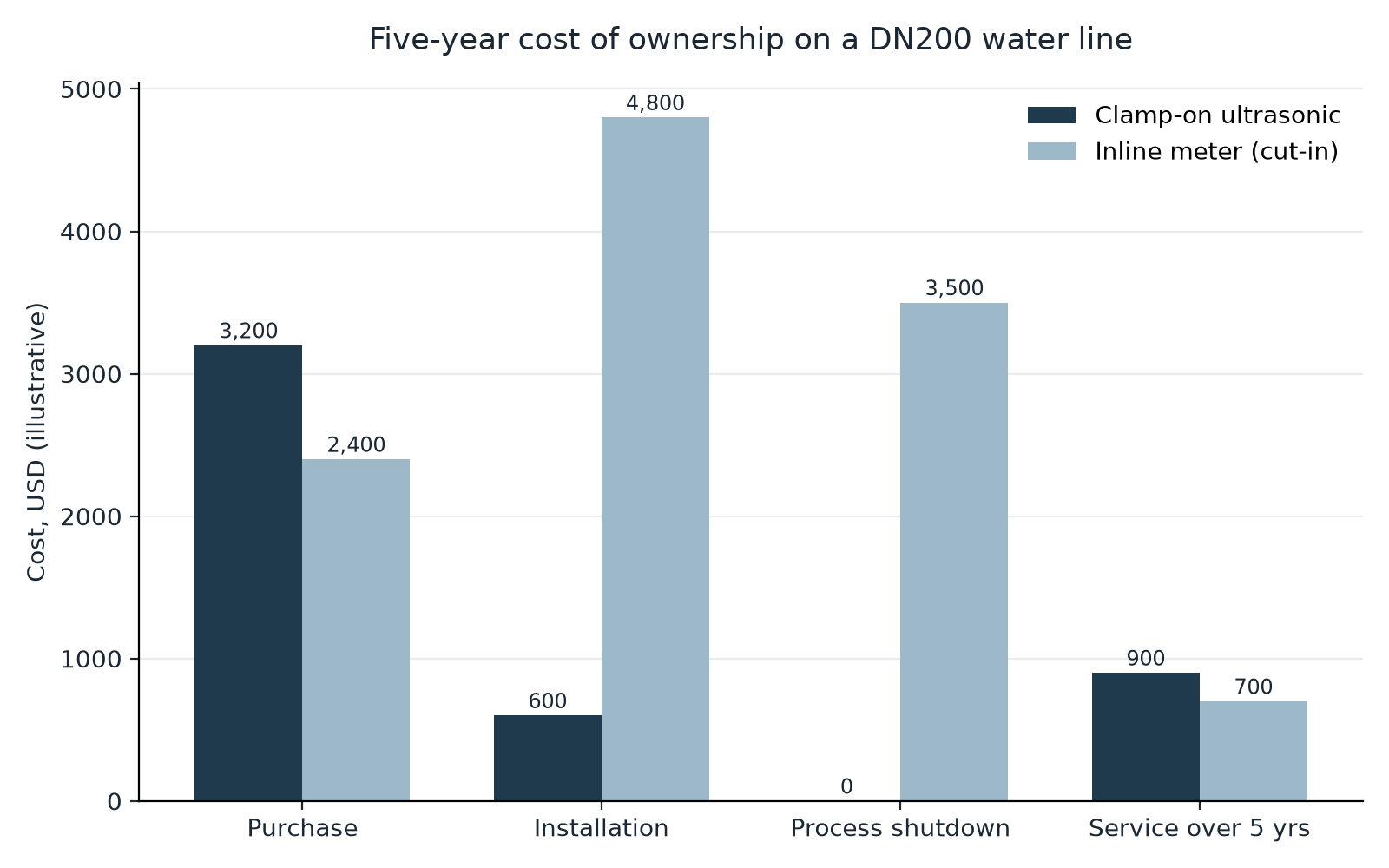
Quick definition: total cost of ownership (TCO) — everything you pay from purchase to retirement: hardware, installation, energy, calibration, spares and the cost of the days the line is down.
Maintenance is modest but real. Couplant dries. On hot lines, plan to refresh it every 12–24 months. On cold water lines, a silicone film can last five years or more. Re-verification is cheaper than recalibration: compare the meter against a portable unit or a tank drawdown, and only send it back when the drift passes your tolerance.
Scalability is the quiet advantage. One clamp-on set can move to a different pipe size with a new spacing entry and, at most, a second transducer pair. A cut-in meter cannot move at all without a shutdown and a welder.
Risk belongs in the same column. A failed inline meter means a cut-out, a spanner and a production stop. A failed clamp-on transducer means a 20-minute swap with the line running. For a utility, that difference is measured in complaints. For an OEM, it is measured in warranty claims.
For a fuller model, including energy and labour assumptions, this cost savings and ROI breakdown walks through the arithmetic.
IX. Vendor Qualification: Questions That Sort Suppliers
Hardware is easy to compare. Support is not. Ask these four questions before you shortlist, and listen for a process rather than a promise.
| Pregunta | A good answer sounds like | A weak answer sounds like |
|---|---|---|
| How is field commissioning handled? | Named engineer, remote session, signal check before sign-off | “The manual explains it” |
| Can frequency be matched to our wall thickness? | A table of pipe ranges and a recommendation per size | One sensor pair for everything |
| What accuracy is guaranteed in our conditions? | A stated figure with reference conditions and exclusions | “±0.5% for all applications” |
| What happens when the reading drifts? | Diagnostic steps, spares lead time, repair route | “It should not drift” |
Ask for documentation at the same time. EPC handover usually needs a calibration certificate, a material certificate for wetted parts where applicable, and a wiring diagram. Utility projects often add a hazardous-area certificate if the area is classified. Getting these at order stage costs nothing. Getting them after shipment costs weeks.
The other filter is honesty about limits. A supplier who says “clamp-on will not work on your 3 mm cement-lined main, use an insertion meter” is more useful than one who quotes a sensor for every line. This list of eight mistakes buyers make with flow meter partners covers the rest of the pattern.
X. Turning the Requirements into a Decision
The ten checks connect. Pipe data feeds the flow calculation. Flow profile feeds the straight run. Straight run feeds the mounting mode. Mounting mode feeds signal quality. Signal quality feeds the accuracy you can honestly quote to a client.
Run the list before you send an RFQ:
- Confirm pipe material, outside diameter and wall thickness from a drawing, not from memory.
- Note the schedule, and check the inside diameter it produces.
- Record the liner type and thickness, if there is one.
- Measure the straight run available, upstream and downstream, in pipe diameters.
- List the liquid, its normal temperature, its pressure and its worst-case air content.
- Decide the accuracy class the application actually needs.
- Pick the output protocol and the power source.
- Choose the mounting mode for the pipe size.
- Ask for the spacing table and the commissioning process.
- Price the five-year cost, not the unit price.
Ten answers turn a clamp-on ultrasonic flow sensor from a catalogue item into a specification. They also make the vendor conversation short, because a supplier can quote with confidence when the pipe data is right.
Jade Ant Instruments works with OEM skid builders, distributors, EPC contractors and utility teams on exactly this sequence, from pipe survey to first validated reading. If you have a line in mind, send the pipe and fluid details and we will tell you which sensor fits, and which one does not.
Terms You Should Know
| Término | Plain meaning | Ejemplo |
|---|---|---|
| Transit time | Time for a sound pulse to cross the pipe | 180 µs upstream, 176 µs downstream |
| Transducer | The crystal that sends and receives sound | A 2 MHz pair for a DN150 steel line |
| Couplant | Grease or paste that carries sound into the metal | Silicone grease on a water line |
| Straight run | Straight pipe before and after the sensor, in D | 10D up, 5D down on a DN200 line |
| V-mount / Z-mount | Transducer layout on the pipe | V for DN50–DN400, Z above that |
| Reynolds number | A number that tells you if flow is laminar or turbulent | 12,000 means turbulent |
| Servicio de preparación de la cama | Lowest to highest flow inside the accuracy band | 100:1 |
| Wet calibration | Checking the meter against a physical master | Gravimetric rig, ±0.2% reference |
PREGUNTAS FRECUENTES
How does pipe wall thickness affect the choice of ultrasonic frequency?
Thick walls absorb high-frequency sound, so a thick wall needs a lower frequency. As a rule, 1 MHz suits walls over 10 mm, 2 MHz covers 4–10 mm, and 4–5 MHz suits thin walls under 4 mm. Wall thickness also sets the path length used in the calculation, so an error there goes straight into the reading.
What percentage of entrained air causes signal loss?
Above roughly 1–2% air by volume, most clamp-on meters start losing signal quality. At 5% or more, transit-time measurement often fails completely. Move the sensor to a section with higher pressure, away from pump discharge and aerated tanks, and the same meter will often read again without any settings change.
How do we stop signal attenuation on HDPE or lined pipe?
Sound travels near 2,400 m/s in HDPE, against about 1,480 m/s in water, so the beam bends at the wall. Use a 1 MHz pair, a Z-mount, and a spacing value taken from the meter’s HDPE table. On cement-lined ductile iron, the liner scatters sound, so clamp-on often fails and an insertion meter is the honest answer.
How do I calculate the minimum straight run for my pipe?
Count in pipe diameters. Allow 10D upstream and 5D downstream as a baseline. Increase to 20D and 10D after two closely spaced elbows, after a partially closed valve, or where the reading feeds billing. If space is short, a flow conditioner can recover some of the loss, but it must sit well upstream of the sensor.
Which acoustic couplant should we use above 150 °C?
Use a high-temperature paste rated above the line temperature, not the standard grease used on cold water lines. Silicone grease is generally good to about 200 °C, but it dries faster as the temperature rises, so a 150–180 °C line may need a fresh film every 6–12 months. Above 200 °C, use paste or a clamped dry-coupling pad.
How do we eliminate interference when the sensor sits next to a high-power pump?
Keep the transducer cable 300 mm or more from motor and VFD cables, cross power cables at 90°, and bond the shield at one end. Use shielded twisted pair, and cut surplus cable instead of coiling it. Then check gain and signal quality at the transmitter. A stable quality figure above 60% usually means the fix worked.
Can clamp-on sensors measure bidirectional flow on a skid?
Yes. Transit-time meters measure the difference between upstream and downstream travel, so reverse flow shows as a negative velocity. Enable the bidirectional mode, set the low-flow cut-off so noise near zero does not totalise, and confirm the totaliser subtracts rather than adds reverse flow. This matters on loading skids and loop-based heating systems.
How do we verify accuracy without interrupting the process?
Compare against a second, independent method: a portable clamp-on meter, a tank drawdown, or a calibrated pump curve at a known speed. A 30-minute comparison at three flow points is usually enough to spot drift. If the deviation stays inside your tolerance band, document it and keep running. Send the unit for wet calibration only when it does not.
How do utilities handle clamp-on sensors in high-vibration or water hammer locations?
Mount the transducers with steel clamps, not straps, and avoid pipe sections downstream of fast-closing valves. Water hammer sends a pressure wave that briefly breaks the acoustic path, so set a short signal-loss delay rather than an instant alarm. On pump headers, move the sensor two to three pipe diameters further downstream and check gain after the first surge event.
What documentation does an EPC project usually require?
Expect a calibration certificate with stated method and traceability, a material certificate for wetted parts where applicable, a wiring and terminal diagram, and a hazardous-area certificate if the zone is classified. Add a factory acceptance test record for skid-mounted units. Ask for the document list at quotation stage so it lands in the vendor document register on time.