Top 5 Analog Flow Meters for Water Applications: A Guide for OEM Equipment Manufacturers
1. Addressing OEM-Specific Challenges in Water Flow Measurement
A water treatment skid can pass a workshop test and still cause trouble on site. The flow reading may jump when a pump starts. The replacement meter may fit the pipe but need a different power supply. A missing drinking-water approval can hold up the whole package.
For original equipment manufacturers (OEMs), these problems add wiring changes, service visits, and delivery risk. Distributors inherit the parts questions. Engineering, procurement, and construction (EPC) teams must resolve them before handover.
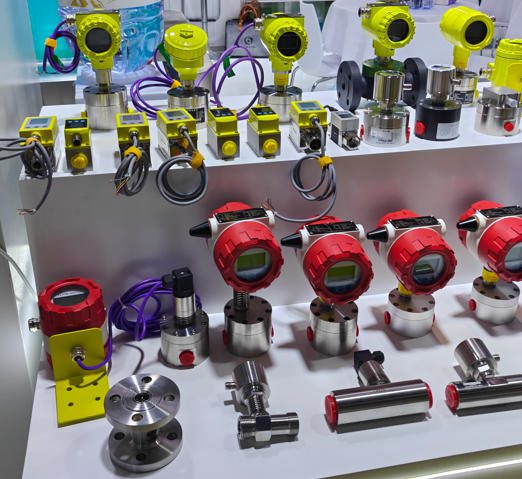
An analog-output water flow meter measures water flow and sends a continuous electrical signal, commonly 4–20 milliamps (mA), to a controller. Its sensing technology may be magnetic, mechanical, or ultrasonic. A digital display does not prevent a meter from having an analog output.
The right choice combines a suitable measuring range, durable wetted materials, and a signal your control panel can accept. It must also fit the skid, remain serviceable, and arrive with the right documents.
2. Why Analog Flow Meters Still Matter in Modern Water Applications
A 4–20 mA loop gives a programmable logic controller (PLC) a flow value through a familiar input. A technician can check that signal with a loop calibrator without setting up a network.
For a skid with one flow-control loop, this can keep panel design and commissioning straightforward. It also suits legacy panels that have spare analog inputs but no convenient digital interface.
Current signals can tolerate cable resistance better than voltage signals, provided the power supply has enough voltage for the complete loop. They still need correct wiring, grounding, and protection from electromagnetic interference (EMI), which is electrical noise from nearby equipment. See the manufacturer’s explanation of 4–20 mA circuit behavior.
Analog does not automatically mean low power or higher reliability. A mechanical indicator may need no electricity, while its transmitter does. A magnetic meter may need a separate supply even when its output is 4–20 mA. For a remote site, calculate the demand of the sensor, transmitter, radio, and any heater together.
HART, a communication protocol that adds digital information to a current loop, can provide setup and diagnostic access when the selected instrument and receiving equipment support it.
3. Selection Criteria: What OEMs and Industrial Clients Must Consider
Start with the operating range
Record minimum, normal, and maximum flow. Include startup, standby, flushing, and the lowest pump speed. A meter sized only for peak flow may give a weak measurement during normal operation.
Precisión describes closeness to the reference value. Repetibilidad describes how consistently the meter reports the same flow under unchanged conditions. Servicio de preparación de la cama is the ratio of maximum to minimum flow over which the stated performance applies.
A range of 5–50 L/min gives 10:1 turndown. It does not prove the meter can measure a 1 L/min standby flow accurately.
| Selection item | Information to send with the inquiry | Problem it helps prevent |
|---|---|---|
| Rango de caudal | Minimum, normal, and peak flow in one unit | Poor low-flow control |
| Water quality | Conductivity, solids, bubbles, and treatment chemicals | Wrong sensing technology |
| Presión y temperatura | Normal values, limits, and cleaning conditions | Seal damage or an unsuitable pressure rating |
| Wetted materials | Required body, liner, electrode, float, and seal materials | Corrosion or approval mismatch |
| Electrical interface | Supply, active/passive loop, load, and cable length | A meter that will not communicate with the panel |
| Instalación | Pipe bore, connection, orientation, and available straight pipe | Rework after fabrication |
| Service and approvals | Calibration needs, destination requirements, and spare parts | Delayed acceptance or repair |
Use a flow meter selection checklist to document these conditions before requesting prices.
Download the water flow meter application checklist to collect the details for your next supplier inquiry.
Check the complete error statement
Illustrative calculation, not a product test: A meter specified at ±0.5% of a 100 L/min full scale has a ±0.5 L/min error allowance. At 10 L/min, that is ±5% of the reading.
A meter specified at ±0.5% of reading would have a ±0.05 L/min allowance at the same flow, before any added fixed term or output error.
This difference matters on a skid that spends most of its time below peak capacity. Review the meaning of flowmeter datasheet terms before comparing accuracy headlines.
Match materials and enclosure protection
Wetted parts are the components that touch the water. Check every one, including seals. A stainless body alone does not establish suitability for chlorinated water, cleaning chemicals, or drinking-water service.
Ingress protection (IP) ratings describe protection against solids and water. Specify the actual exposure: indoor splashes, outdoor washdown, or pit flooding. For immersion, obtain the permitted depth and duration. Do not assume an IP rating and a NEMA enclosure rating are interchangeable.
4. Top 5 Analog Flow Meters for Water Applications
These five options form an application shortlist, not a performance ranking. Outputs, approvals, and service features depend on the ordered configuration.
1. Siemens SITRANS FM MAG 1100 with a Compatible Transmitter
Best fit: compact process-water skids using conductive water.
The MAG 1100 is an electromagnetic sensor. This technology measures the voltage produced as conductive water moves through a magnetic field. Conductivity means the water’s ability to carry electrical current.
Siemens lists ceramic or PFA liners for this sensor family. PFA is a fluoropolymer used as a chemically resistant lining. The sensor must be paired with a compatible transmitter to provide the required electrical outputs. Review the MAG 1100 operating instructions for the selected assembly.
For OEM integration, its compact construction and lack of a moving rotor make it worth considering where access is tight. Check installation length, grounding arrangements, and access to the transmitter cover before releasing the skid drawing.
Main limitation: Do not specify it for very low-conductivity purified water without checking the complete system’s conductivity limit. “Clean water” and “conductive water” are different requirements. Confirm 4–20 mA and any HART capability in the transmitter order code.
2. Endress+Hauser Proline Promag W 400
Best fit: water and wastewater packages where verification and documentation matter.
The Promag W 400 is a magnetic meter designed for water service. Available configurations include 4–20 mA HART. The published enclosure options include IP66/67 and an optional IP68 remote sensor arrangement.
Its Heartbeat Technology provides integrated verification and build-up detection. Build-up means deposits on the measuring surfaces. These features can help a maintenance team assess instrument condition between planned interventions. Confirm the required options through the Promag W 400 product specifications.
For an EPC project, the useful question is whether the selected configuration can produce the records the owner needs at handover. For a skid builder, check whether its size, wiring access, and installed flow conditions fit the package.
Main limitation: Verification does not automatically replace a flow calibration. Do not assume self-cleaning electrodes, hazardous-area approval, or zero-straight-run performance across every configuration.
3. Badger Meter ModMAG M2000
Best fit: industrial water systems that need a broad size range and field verification.
The M2000 is an electromagnetic meter, not a turbine meter. Its family offers different liners and electrode materials, allowing the wetted assembly to be matched to the water and process conditions.
Badger describes the platform as suitable for field verification with a handheld device. This can help maintenance, repair, and operations (MRO) teams plan checks without relying only on a panel reading. Use the ModMAG M2000 technical resources to obtain the exact amplifier, analog-output, and installation documentation before ordering.
One useful specification detail concerns short pipe runs. Badger publishes ±1% accuracy with zero straight run and ±0.2% with the required straight run for the stated application conditions. That is a practical reason to compare installed performance, rather than one catalog number. See its M2000 installation-dependent accuracy guidance.
Main limitation: Confirm the precise sensor/amplifier package and its current-output wiring. Do not apply a headline accuracy value outside the stated conditions.
4. KROHNE H250 M40 with a 4–20 mA Module
Best fit: clean-water auxiliary lines needing local indication and a remote signal.
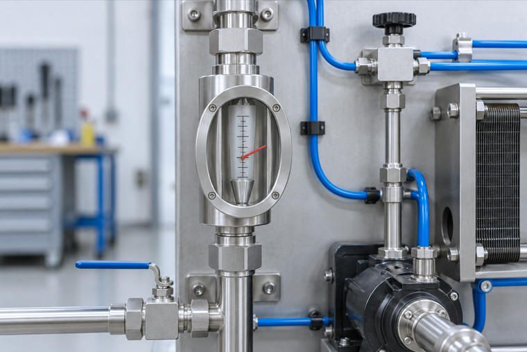
A variable-area meter uses a float whose position changes with flow. In a metal-tube design, that movement drives an external indicator. It gives a field technician a local reading without needing to look at the control panel.
The H250 M40 has a modular design. KROHNE lists a two-wire 4–20 mA module and limit-switch options in its H250 M40 electronics overview.
Consider it for cooling-water branches, pilot equipment, or other clean-water duties where visible flow indication is useful. Confirm the measuring range and approved orientation for the chosen version.
Main limitation: The float must move freely. Deposits, solids, and changes in fluid properties can affect performance. Local mechanical indication may operate without electricity, but remote transmission still requires power. It is not automatically a drop-in replacement for another meter.
5. Seametrics EX100/200 with an FT440 Indicator/Transmitter
Best fit: larger conductive-water pipes where an insertion sensor is practical.
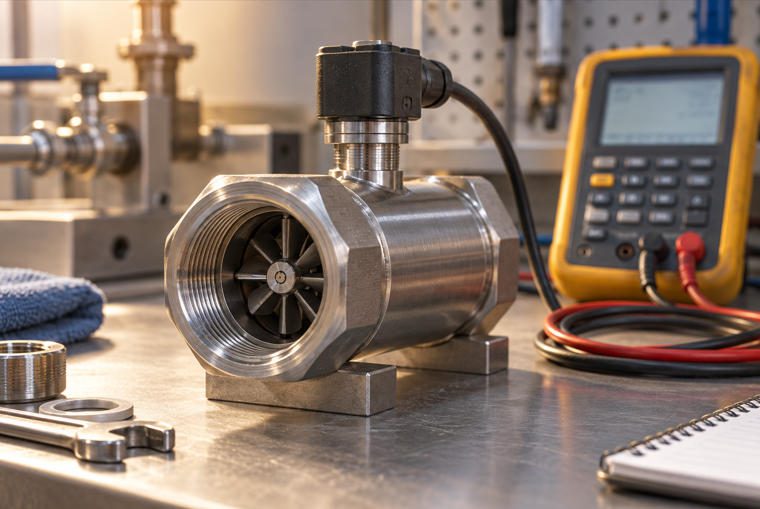
An insertion meter places a sensing probe inside the pipe instead of using a full-bore measuring section. The EX100/200 is electromagnetic, so it has no turbine bearings to service.
The published pipe range is 3–48 inches, with larger sizes optional. Its sensor produces a frequency signal. An FT440 provides the 4–20 mA interface; the complete bill of materials must also account for sensor power. These distinctions appear in the EX100/200 configuration datasheet.
This arrangement can suit municipal and industrial retrofits where replacing a large pipe spool would be difficult. Some related hot-tap variants support service through an isolation valve, but that capability must be specified.
Main limitation: Accuracy depends on the pipe’s actual internal diameter, probe depth, and flow profile. Do not assume every insertion model can be removed under pressure.
Comparison at a Glance
| Shortlisted assembly | Water duty to assess first | Integration priority | Service priority |
|---|---|---|---|
| MAG 1100 + compatible transmitter | Conductive process water | Transmitter, conductivity, and mounting fit | Grounding and access |
| Promag W 400 | Water and wastewater | Selected output and enclosure | Verification records and deposit checks |
| ModMAG M2000 | Industrial and utility water | Installed accuracy and amplifier configuration | Field verification |
| H250 M40 + current module | Clean auxiliary water | Range, orientation, and loop power | Float movement and scale condition |
| EX100/200 + FT440 | Larger conductive-water pipes | Pipe bore, depth, and sensor power | Safe probe access |
5. Integration Tips for Skid-Mount and OEM Applications
Prove the current loop before running water
An active output supplies current. A passive output needs an external source. Match the transmitter arrangement to the PLC input and avoid unintentionally connecting two supplies.
For an illustrative 0–100 L/min range:
| Test current | Expected PLC reading |
|---|---|
| 4 mA | 0 L/min |
| 8 mA | 25 L/min |
| 12 mA | 50 L/min |
| 16 mA | 75 L/min |
| 20 mA | 100 L/min |
This test checks electrical scaling. It does not test the sensor’s flow accuracy. Also confirm the configured fault current and the PLC alarm response.
Put installation requirements into the drawing
Show the flow direction, orientation, and pipe-full requirement.
Reserve the straight pipe required for the exact meter and upstream fittings.
Show grounding or potential equalization, which keeps the meter and process at the required electrical reference.
Leave room to remove covers, clean sensors, and replace gaskets.
Route instrument cables away from variable-frequency drives, which control motor speed and can introduce electrical noise.
Follow the manufacturer’s shield termination instructions. For long routes or differing ground potentials, assess isolation, surge protection, cable resistance, and the loop voltage budget.
Installation video: Watch M2000 magnetic flow meter orientation tips on YouTube. Use the video as an introduction and the selected meter’s manual for final installation requirements.
6. Common Installation Errors and How to Avoid Them
| Error | Likely symptom | Corrective action |
|---|---|---|
| Air collects at the meter | Unstable or implausible reading | Keep the measuring section full and arrange suitable air removal |
| Meter follows a disturbing elbow or valve | Repeatable measurement bias | Meet the model-specific installation conditions |
| Turbine is sized only by pipe diameter | Weak low-flow response | Select by operating range and allowable pressure loss |
| Poor potential equalization | Noise or apparent zero drift | Inspect the prescribed bonding and grounding arrangement |
| PLC and transmitter use different ranges | Smooth but incorrect reading | Test current and engineering-unit scaling together |
| Excessive signal damping | Slow response to changing demand | Set filtering to suit the process response time |
Do not open a meter vent or loosen a fitting on a pressurized line to diagnose bubbles. Use the system’s approved venting and isolation arrangements.
A useful troubleshooting distinction: If the meter display is stable but the PLC value is not, inspect the signal path first. If both values move together, investigate the process, sensor, and installation. This does not prove the cause, but it helps choose the next test.
7. Maintenance and Calibration: Ensuring Long-Term Performance
Calibration compares the meter against a reference under stated conditions. Verification checks whether the device meets defined tests. A simulated current-loop check tests the electrical path. Keep these three records separate.
A 12–24 month review interval can be a planning starting point for a noncritical application, subject to the manufacturer’s guidance. It is not a universal recalibration requirement. Set the actual interval from process risk, operating history, owner requirements, and any applicable rules.
For magnetic meters, inspect deposits, seals, connections, and grounding. For turbine meters used elsewhere in the plant, inspect the rotor and bearings and maintain any specified upstream strainer. For variable-area meters, check float movement and readability.
Keep serial numbers, settings, calibration results, verification reports, and service dates together. Record results before adjustment so that drift remains visible.
For traceability, ask for the reference chain and measurement uncertainty. NIST’s explanation of metrological traceability describes the documented chain of calibrations involved. A “NIST-traceable” label alone does not tell you whether the calibration is suitable for your acceptance limits.
8. Compliance and Certification: Meeting Global Water Standards
Buy against the exact assembly and destination requirements. A product family’s certificate list does not establish that every liner, seal, size, and connection is covered.
| Market or duty | Evidence to review | Scope to check |
|---|---|---|
| Drinking-water contact | NSF/ANSI/CAN 61 health-effects requirements | The listed product and permitted contact conditions; this is not a flow-accuracy certificate |
| UK water installations | WRAS approval directory | Exact product or material listing and installation conditions |
| German drinking-water applications | UBA evaluation criteria for water-contact materials | Applicable material criteria, including KTW-BWGL for organic materials |
| French drinking-water applications | French sanitary conformity evidence | Applicable ACS or other evidence for the material or assembly |
| Classified hazardous areas | Relevant ATEX documentation and IECEx equipment certification | Exact equipment marking, zone, gas or dust group, temperature limits, and installation conditions |
ATEX and IECEx address equipment for potentially explosive atmospheres. Wastewater service alone does not establish a hazardous-area classification. Use the project’s area classification to select the complete instrument assembly and accessories.
9. Supply Chain and Lead Time Considerations for Distributors and OEMs
“In stock” is useful only when it refers to the approved order code. A sensor may be available while its transmitter, special liner, flange, or certificate package is not.
Request a dated quotation that separates instrument availability, document approval, testing, and shipment. Do not use a generic online lead time as a project commitment.
For repeat skid builds, standardize a small set of approved ranges, connections, outputs, and spare parts. Keep a controlled record of the configuration supplied on each skid.
Dual sourcing requires engineering work. Two meters with 4–20 mA outputs may differ in installation length, power, low-flow performance, pressure loss, or fault behavior. Validate the alternate before a shortage forces a substitution.
For urgent customization, freeze the mechanical interfaces and electrical requirements first. Ask the supplier to identify changes that affect testing, approval scope, and delivery. A quick drawing change can still require a longer production or certification process.
10. Partnering with the Right Supplier: Beyond the Product
A useful supplier response should let your team complete the drawing, wire the panel, and plan the first service visit.
Ask for the following deliverables:
A configured datasheet showing the actual operating range and error statement.
Dimensioned drawings or CAD models, including service clearances.
Wiring details, power demand, output scaling, and fault behavior.
Calibration and approval documents tied to the ordered assembly.
A commissioning procedure and a named route for technical support.
Spare-part codes, expected availability, and training options for field teams.
When discussing a project with Jade Ant Instruments, send the water chemistry, flow range, pressure, temperature, connection drawing, and PLC input details together. The company’s industrial flow measurement offering includes several sensing technologies and OEM configuration support. Ask for the proposed model’s evidence rather than assuming every family has the same performance or approvals.
For distributors and importers, include destination documentation and local service needs. For industrial end users and utilities, include the shutdown window and the parts your maintenance team can replace on site.
Technical Terms in Plain English
| Término | Meaning | Ejemplo |
|---|---|---|
| Conductivity | How easily water carries electrical current | A magnetic meter needs water above its specified conductivity limit |
| Wetted parts | Parts that touch the water | Liner, electrodes, seals, and float |
| Servicio de preparación de la cama | Maximum flow divided by minimum flow at stated performance | 50 ÷ 5 L/min = 10:1 |
| Full-scale error | Error based on the range maximum | 0.5% of 100 L/min = 0.5 L/min |
| Loop load | Resistance the current output must drive | Cable plus PLC input and other series devices |
| Flow profile | How water speed varies across the pipe | An elbow can distort the profile seen by an insertion probe |
| FAT | Factory acceptance test before shipment | Check wiring, settings, documents, and agreed functional tests |
| SCADA | A system for remote monitoring and supervisory control | A utility control room receiving flow values from pump stations |
Preguntas frecuentes
1. Why choose an analog-output flow meter over a digital-only meter?
Choose it when the existing panel accepts 4–20 mA and one flow value meets the control need. It can simplify integration. It does not automatically offer lower cost, better accuracy, or greater noise immunity than every digital option.
2. Can analog flow meters be used in potable water systems?
Yes, when the exact wetted assembly meets the destination’s drinking-water requirements. Verify the certificate scope, materials, operating conditions, and any owner-specific requirements.
3. What is the typical accuracy of an analog magnetic water flow meter?
Industrial magnetic meters often publish sub-1% reference-condition specifications, but the complete error formula matters. Include any fixed velocity term, analog-output error, and PLC input error when assessing the required system performance.
4. How do I keep the signal stable over long cable runs?
Check the loop voltage budget, use the specified cable, separate it from motor-power wiring, and follow the grounding instructions. Add suitable isolation or surge protection where the installation requires it.
5. Can analog-output meters measure wastewater containing solids?
Suitable electromagnetic meters can measure conductive wastewater with solids. Confirm the solids content, abrasiveness, deposit risk, and gas content. The pipe must meet the selected meter’s filling and installation requirements.
6. What maintenance does a turbine flow meter need?
Inspect the rotor and bearings, remove deposits using approved methods, and maintain the specified strainer. Increasing error at low flow is a reason to investigate wear, fouling, or changed process conditions.
7. Can I retrofit a meter into an existing skid?
Often, but verify connection size, installation length, flow range, straight pipe, power supply, and PLC compatibility. Matching the connection thread alone does not make a replacement suitable.
8. Do analog flow meters support remote monitoring?
Yes. A PLC or remote terminal can read 4–20 mA and send the value to a SCADA system. The current loop itself does not provide an internet or radio connection.
9. Why does turndown matter for an OEM water skid?
It shows whether the meter can cover both normal and reduced flow at the stated performance. Check the lowest operating point explicitly; a broad advertised range may include conditions with a different error limit.
10. How do I select an insertion meter for a large pipe?
Use the actual internal diameter, pipe material, available straight run, and flow range. Set probe depth according to the manual and specify the mounting fitting and safe service arrangement.
11. Are hazardous-area versions available?
Some flow meter families have suitable certified versions. Select against the area’s classification and the exact certificate. A weatherproof enclosure does not establish explosion protection.
12. How long will an industrial water flow meter last?
There is no reliable universal lifespan. Water chemistry, wear, flooding, temperature, vibration, and electronics support all matter. Build the maintenance and replacement plan around operating history and parts availability.
13. Can distributors obtain technical training?
Ask the manufacturer or authorized channel for available training. Specify the topics needed: sizing, configuration, loop testing, fault diagnosis, and spare-part replacement. Confirm any certification claim in writing.
14. Is a traceable calibration certificate always included?
No. State the required certificate, test points, uncertainty, and laboratory accreditation in the purchase specification. Confirm whether it is included in the quote or supplied as an option.
15. How can EPC teams reduce commissioning delays?
Approve the configured datasheet, installation drawing, wiring, and compliance documents before shipment. During acceptance testing, record output scaling, alarm behavior, serial numbers, and agreed flow-test results in one handover package.
Conclusion: Empowering OEMs with the Right Flow Measurement Partner
Start with the water and the operating range. Assess the MAG 1100 for compact conductive-water duties, Promag W 400 for water and wastewater projects needing verification features, and M2000 for industrial and utility systems. Consider H250 M40 where local indication helps field work, and EX100/200 with FT440 where insertion measurement suits a larger pipe.
Then compare the installed result: low-flow performance, mechanical fit, electrical compatibility, documents, and service access. These determine how much work remains after the meter arrives.
For your next skid, replacement project, or distribution inquiry, request a water flow meter application review from Jade Ant Instruments. Include your minimum, normal, and maximum flow plus the water chemistry and piping drawing so the proposed configuration can be checked against the job.