A Practical Guide for B2B Flow Instrumentation Distributors and Agents

A high-EMI industrial installation — variable-frequency drives, high-current busbars, and instrument cables sharing the same physical space create the interference conditions that most standard flow meters are not designed to handle.
A water utility in Southeast Asia recently discovered that every flow meter across 14 distribution substations had been reading 3–4% high for eleven months. The culprit was not a faulty meter, not a calibration error, and not operator neglect. It was a variable-frequency drive (VFD) installed on the adjacent pump station three months earlier — and nobody had assessed the electromagnetic interference (EMI) that VFD would produce. By the time the discrepancy was traced and quantified, the billing exposure had compounded to approximately $340,000, a number that surfaces in internal post-mortems but rarely gets shared at industry conferences.
This is how EMI damage works: it is invisible, it is cumulative, and it is almost always misattributed until someone runs the numbers carefully. The meter looks fine. The transmitter throws no alarms. The readings drift by 2%, then 3%, then settle at a level that nobody notices because the process hasn’t changed dramatically enough to trigger suspicion. Six months later, a mass balance audit doesn’t close, or a regulatory report flags an inconsistency, and the investigation begins — pointing backward to a specification conversation your sales team had 14 months ago.
For B2B distributors and agents who supply flow instrumentation to industrial clients, this problem has a concrete commercial dimension that goes beyond technical interest. When a meter underperforms due to EMI interference, the customer doesn’t think “our electromagnetic environment caused this.” They think “the meter failed.” That perception attaches to you — regardless of whether the meter was perfectly manufactured, correctly calibrated, and properly specified for the process fluid. The environment, which your customer controls and which you may never have assessed, becomes your commercial liability the moment the complaint arrives.
This guide addresses that problem directly. It explains how EMI disrupts flow measurement across different meter technologies, how your sales and service teams can identify interference problems before they become expensive disputes, what specifications actually differentiate a genuinely EMI-resistant meter from one relying on marketing language, and how EMI expertise — once built — becomes one of the few competitive advantages in industrial instrumentation that price competition cannot erode.
Understanding EMI and What It Actually Does to a Flow Meter
Electromagnetic interference, in its simplest form, is electrical noise generated by one device that corrupts the signals of another. Every industrial facility generates it continuously. The sources are not exotic: motor drives, welding arcs, power transformers, high-current busbars, and increasingly, the wireless infrastructure of industrial IoT deployments. The problem is not that these sources exist — it is that most flow meter installations were designed without accounting for them systematically.
EMI travels in two distinct forms, and understanding the difference matters when you’re diagnosing a problem in the field. Conducted EMI moves through shared wiring and ground connections — when a VFD’s switching noise travels along a power cable that shares a conduit with an instrument cable, that is conducted interference. Radiated EMI propagates through the air as an electromagnetic field, inducing current in cables and sensor circuits without any physical connection — the same principle by which a radio antenna receives signals, but in this case the “antenna” is your customer’s unshielded instrument cable. Recommending the wrong corrective measure wastes the customer’s budget and leaves the original problem unresolved, which is why diagnosing the transmission pathway matters as much as identifying the source.
The most common EMI sources in modern industrial environments are VFDs — specifically the high-frequency switching noise generated by pulse-width modulation (PWM) at 4–16 kHz that forms the basis of their motor control. A modern industrial plant running energy-efficient variable-speed pumping may have 20, 30, or 50 VFDs operating simultaneously, each one generating conducted and radiated noise across a broad frequency range. Arc welding equipment generates broadband impulse interference that couples into nearby instrument cables during operation. Large electric motors produce transient voltage spikes during starting that can saturate a meter’s input circuits momentarily. And across the entire facility, the 50/60 Hz power line frequency creates a constant low-level induction field in any cable routed parallel to power distribution wiring.
The 5G Industrial IoT market, valued at approximately $14.65 billion in 2025 and projected to grow substantially through 2034, is adding a new layer to this problem. As industrial facilities deploy wireless communication infrastructure — 5G private networks, WirelessHART sensor networks, industrial Zigbee systems — the ambient radio frequency environment inside those facilities becomes measurably more complex. Each additional wireless transmitter is an additional EMI source, and the frequencies involved (sub-6 GHz and millimeter wave for 5G, 2.4 GHz for most industrial wireless protocols) overlap with the signal processing frequencies of several flow meter technologies.
How EMI Enters the Signal Chain in Different Meter Technologies
Not all flow meters are equally vulnerable to electromagnetic interference, and the reason is technical: the measurement principle of each technology determines where interference can enter the signal chain, which in turn determines what protective strategy is most effective. Understanding this technology-specific vulnerability is the foundation of intelligent specification — and of credible technical conversations with customers whose facilities have complex electrical environments.
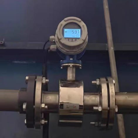
Electromagnetic flow meters — mag meters — measure flow using Faraday’s Law: a conductive fluid moving through a magnetic field generates a voltage proportional to its velocity across two electrodes. That induced voltage is typically in the millivolt range, which is precisely the problem. The measurement signal is small enough that any external electromagnetic field coupling into the electrode circuit or signal cable adds noise that the transmitter cannot reliably distinguish from the measurement. In a high-EMI environment near large VFDs, this coupling can produce output swings of 3–5% or more from a perfectly calibrated meter. The customer sees measurement drift. They call you. And unless you understand the mechanism, neither party knows where to look.
The specific indicators that distinguish EMI-related drift from genuine meter degradation in a mag meter are diagnostically important. An EMI problem typically produces fluctuations that correlate with nearby electrical events — output swings that appear when the VFD ramps up, stabilize when it holds speed, and shift again during deceleration. A zero-flow test, conducted by closing isolation valves to achieve confirmed zero flow and observing the meter output, is the most direct diagnostic: any non-zero reading at confirmed zero flow indicates a noise floor, meaning the interference environment is adding a permanent offset to the measurement signal. That test costs ten minutes and either confirms or eliminates EMI as the root cause before any hardware is replaced.
Ultrasonic flow meters measure flow by comparing the transit time of ultrasonic pulses sent upstream and downstream through the flowing fluid. The drive and receive electronics operate at frequencies from 100 kHz to several megahertz — ranges that overlap with VFD harmonics, industrial wireless transmitters, and motor drive circuitry. When EMI at these frequencies couples into the transducer drive circuit or signal processing electronics, it disrupts the timing measurements that determine flow velocity. Nanosecond-level timing errors translate into measurable velocity errors in transit-time calculations, and in severe interference environments the meter may lose signal lock entirely, outputting zero or a fault value. For clamp-on ultrasonic meters — the non-invasive design popular for retrofit applications — the transducer leads run along the pipe surface where they are exposed to the pipe’s own electrical noise environment, and heavy EMI can be picked up and amplified through the signal chain in ways that produce phantom reflections the meter’s processor interprets as flow-condition changes.
Turbine flow meters measure flow by counting rotor blade pulses from a spinning rotor. The measurement principle is mechanical and inherently more EMI-resistant than electromagnetic or ultrasonic methods — but the pulse signal produced by the pickup coil is still an electronic signal, and it is susceptible to interference at similar frequencies. The pickup coil and its cable function as an antenna, and EMI at frequencies near the expected pulse rate can induce phantom pulses that cause the meter to over-read. In facilities with large cycling motors near the pulse cable routing, this over-reading can be systematic and difficult to separate from calibration error without a deliberate EMI investigation.
Coriolis flow meters vibrate a measurement tube at its resonant frequency and detect the phase shift created by the Coriolis force of the moving fluid. The drive electronics maintain the tube at precise resonance, and the detection electronics measure phase shift at the same frequency. Strong external vibration or electromagnetic fields at or near the resonant frequency create phase shift artifacts that appear as mass flow errors. The practical implication for distributors: Coriolis meters installed on highly vibrating structures — near reciprocating compressors, for example — require both mechanical isolation and EMI assessment, because both vibration and electrical interference affect the same measurement mechanism through different pathways.
The Jade Ant Instruments product range, which spans electromagnetic, vortex, turbine, and ultrasonic flow meters, addresses EMI vulnerability differently across these technologies, with grounding architectures, shielding specifications, and signal processing capabilities that vary by product line. Understanding those specifications — not as marketing claims, but as technical parameters tied to specific IEC test standards — is what allows your team to make defensible product recommendations for high-EMI environments.
The Financial Reality of EMI-Induced Measurement Errors
The reason EMI resistance matters commercially is not primarily technical — it is financial. Measurement errors compound into real losses that are fully quantifiable, and quantifying them for your customers is the most effective sales technique available in this product category.
For billing and custody transfer applications, the arithmetic is direct. A facility processing $5,000,000 in annual throughput with an EMI-induced measurement error of 2% faces a billing exposure of $100,000 per year — either overpaying for material they’re not receiving, or underbilling for material they’re supplying. The Jade Ant Instruments custody transfer flow meter guide documents that a 0.25% measurement error at a mid-sized natural gas distribution station can generate nearly $500,000 USD in annual financial impact at $3/MSCF. An EMI-induced drift that pushes errors to 1–2% amplifies that exposure by a factor of four to eight. These are not theoretical risks — they are the numbers that appear in billing audit findings and regulatory examination reports.
For process control and quality applications, the cost pathway is through batch failures and rework. A chemicals manufacturer whose dosing meter reads 3% high because of EMI interference from an adjacent VFD will produce batches with 3% less active ingredient than specified. Depending on the application, that manifests as off-spec product, customer returns, regulatory non-compliance, or process yield losses — each of which carries costs that dwarf the price premium for a properly EMI-hardened meter. The case study documented by Jade Ant Instruments on wrong flow meter selection in a chemical manufacturing context — resulting in $847,000 in total losses from a single specification error — illustrates the compounding dynamic: the meter cost was modest, the error was systematic, and it ran undetected long enough to create losses across 18 months of production.
For regulated industries, the cost is also regulatory. EPA 40 CFR Part 98 greenhouse gas reporting requires 5% measurement accuracy. A flow meter with EMI-induced drift exceeding that threshold produces non-compliant regulatory records even when the meter itself is perfectly calibrated — the regulatory violation attaches to the measurement outcome, not to the cause. In pharmaceutical manufacturing, FDA 21 CFR Part 11 requires accurate electronic records for validated processes, and systematic measurement errors triggered by EMI create GMP violations that can result in warning letters, consent decrees, and production shutdowns whose costs are measured in millions.
The distributor’s exposure in all of these scenarios is commercial rather than strictly legal in most jurisdictions, but the commercial consequences are severe and lasting. A customer who experiences a billing dispute traceable to meter performance does not return to the supplier who recommended that meter. In the tight industrial markets where most flow instrumentation distributors operate, that lost account carries a lifetime value of $30,000–$150,000 in foregone revenue — multiples of the margin on any individual transaction.
Identifying EMI Problems in the Field Before They Become Disputes
The most valuable diagnostic service your technical team can offer is identifying EMI as a root cause before a customer blames the meter and demands replacement. This requires a disciplined diagnostic approach and a clear understanding of what distinguishes interference-induced behavior from genuine hardware degradation.
The decisive field test is what might be called the source isolation test: with the flow stable, identify the primary suspected EMI source — typically the VFD, the welding station, or the large motor — and observe whether the measurement instability changes when that source is turned off or load-reduced. If the measurement stabilizes when the VFD ramps down, or if output fluctuations are absent during a weekend when the welding equipment is idle, the root cause is EMI, not meter failure. Document this test in writing before any recommendation is made. This documentation is your warranty protection and your technical credibility with the customer.
A secondary technique uses the meter’s own diagnostic outputs to distinguish environmental interference from hardware failure. Most modern transmitters provide diagnostic signals that report on hardware condition independently of the measurement output: electrode resistance readings for mag meters, signal quality index for ultrasonic meters, tube drive gain for Coriolis meters. A meter with deteriorating hardware shows abnormal diagnostic readings regardless of the EMI environment. A meter whose hardware is functioning correctly but whose measurement output is corrupted by interference shows normal hardware diagnostics — the electronics are healthy, the environment is the problem. This distinction is critical because it determines whether the appropriate response is hardware replacement (hardware failure) or installation remediation (EMI problem).
Before any site visit for an EMI-related complaint, gather specific information from your customer: when did the measurement problems first appear, and what electrical changes preceded them? Does the output instability correlate with specific equipment operating states? Can the customer provide oscilloscope screenshots of the meter output signal? What does the meter’s own diagnostic display show during the unstable periods? This information — which costs nothing to collect — typically narrows the root cause to one or two candidates before your technician arrives at the site, making the investigation more efficient and the resolution more credible.
The four most diagnostically revealing symptoms of EMI interference in flow meters are: output fluctuations that correlate with the operating cycle of nearby electrical equipment, non-zero readings during confirmed zero-flow conditions, measurement values that diverge from mass balance expectations only during specific production periods, and sporadic communication errors or display glitches that appear when large motors start. Each of these symptoms can also appear for other reasons, but their combination — especially with correlation to electrical events — constitutes strong diagnostic evidence for EMI as the primary factor.

Verifying cable shield grounding continuity — a ten-minute check that prevents the majority of EMI-related measurement problems encountered after installation.
The most expensive misdiagnosis in EMI troubleshooting is replacing the meter when the installation environment is the actual problem. The replacement meter exhibits identical behavior in the same unresolved interference environment. The customer’s confidence in your technical judgment drops sharply — not because you recommended a defective product, but because you failed to diagnose the problem correctly before recommending an expensive intervention. The distributor who asks “when did this start and what changed in your facility?” before reaching for the order form demonstrates diagnostic depth that builds lasting trust.
Cable Shielding, Grounding, and Physical Installation: Where Most Problems Are Actually Created
The majority of EMI-related flow meter problems in industrial installations are not caused by inadequate meter specifications — they are caused by incorrect installation practices that defeat whatever EMI protection the meter does have. A premium meter installed with an improperly grounded cable shield performs no better in a high-EMI environment than a commodity meter. Understanding installation requirements and communicating them to customers before delivery — not after a complaint — is one of the highest-return investments your technical team can make.
The mechanism of cable shield failure is worth understanding precisely because it is so counterintuitive. A shielded cable with its drain wire connected to ground at both ends — which sounds like more protection — actually creates a ground loop: a closed conductive path through which 50/60 Hz current circulates, generating a voltage that appears on the signal cable as measurement noise. The correct approach is single-point grounding: the shield drain wire is connected to instrument earth at the transmitter end only, with the sensor end left electrically floating. This configuration allows the shield to intercept induced current and route it to ground at one point without creating a circulating current loop. Every field technician who installs flow meters needs to understand this principle and apply it consistently — and most standard installation training does not cover it explicitly.
The quality of the ground connection matters as much as its topology. A nominal connection to structural steel or to the nearest process equipment ground may measure adequate resistance with a standard continuity tester but still be a high-impedance path for the high-frequency interference that VFDs generate. A proper instrument earth — a dedicated grounding conductor routed directly to the facility’s instrument earth bus, with connection impedance measured below 1 ohm at the relevant frequency — provides dramatically better high-frequency protection than structural grounds even when the DC resistance is similar. In facilities with poor instrument grounding infrastructure, this single correction resolves a large proportion of EMI-related measurement problems without any hardware changes.
Physical separation between signal cables and power cables is the first line of defense and often the most undervalued. The IEC 61000-5-6 installation standard recommends a minimum 100 mm separation from low-voltage power cables and 300 mm from high-voltage circuits. Where crossing is unavoidable, signal cables should cross power cables at 90 degrees — never run parallel. The electromagnetic field from a power cable falls off roughly as the square of distance, meaning that doubling the separation reduces the induced voltage by approximately 75%. Routing a signal cable in a dedicated metal conduit adds 20–30 dB of attenuation beyond cable shielding alone — adequate for most industrial EMI environments without any change to the meter specification.
The minimum physical separation requirements between flow meter transmitters and common EMI sources represent practical installation guidance that your team should include in every technical specification package and delivery document. A VFD cabinet requires 3 meters of separation from the transmitter and 1 meter from the signal cable, with greater separation if the drive exceeds 75 kW. An arc welding station requires 5 meters of separation from both the transmitter and signal cable, and ideally welding operations should be scheduled during off-hours when the flow meter is not in critical measurement service. A high-voltage transformer exceeding 100 kVA requires 5 meters of separation, accounting for the fact that magnetic fields from large transformers can propagate through building structures rather than simply through air. A high-current busbar exceeding 100 amperes requires 1 meter of clearance from signal cables, routing perpendicular to rather than parallel with the busbar run.
Including a laminated one-page summary of these separation requirements with every flow meter delivery — formatted as a quick-reference card rather than an engineering specification — is a low-cost customer value-add that prevents a disproportionate number of post-installation complaints. It also creates a documentary record that your team communicated the installation requirements, which protects your warranty position if a complaint arises from a customer who ignored the guidance.
EMI Specifications That Actually Differentiate Products
The instrumentation market is filled with meters described as “industrial grade,” “EMI-hardened,” or “suitable for harsh electromagnetic environments.” These descriptions are marketing language without standardized meaning. The specifications that enable genuine comparison across manufacturers are defined by IEC 61000-4-X test standards — specific test conditions, specific field levels, and specific pass/fail criteria that are reproducible and verifiable by independent laboratories.
The most relevant IEC 61000 immunity specifications for flow meter procurement are: radiated immunity per IEC 61000-4-3, which tests the meter’s performance in an applied electromagnetic field at specific frequencies — a minimum of 3 V/m for basic industrial suitability and 10 V/m for robust protection in VFD-intensive environments; conducted immunity per IEC 61000-4-6, which tests susceptibility to interference injected through signal and power lines — again, 10 V/m is the threshold for genuine industrial robustness; fast transient burst immunity per IEC 61000-4-4, which tests response to the rapid voltage transients generated by switching motor control circuits — 2 kV is the appropriate level for applications near motor starters and contactors; and surge immunity per IEC 61000-4-5, which covers the longer-duration transients from lightning and grid switching events — 2 kV line-to-line is the relevant industrial threshold.
Compliance with IEC 61000-6-2, the generic immunity standard for industrial environments, integrates these individual test requirements into a single compliance framework. A meter that carries genuine IEC 61000-6-2 compliance has been tested against all major industrial interference sources in a controlled, reproducible manner. This is the baseline specification that every meter supplied into a serious industrial application should meet — not a premium option, but a standard qualification requirement. Compliancetesting.com’s guide to IEC 61000-6-2 explains the specific test requirements in accessible language and is worth sharing with customers whose procurement teams question why EMC compliance matters for flow instrumentation.
The distinction between self-declared CE marking and third-party certified compliance is commercially important for distributors in markets with sophisticated procurement teams. A CE self-declaration requires no independent verification — the manufacturer assesses their own compliance against their own test data. A CE marking with a supporting test report from an ISO/IEC 17025-accredited laboratory documents the specific test conditions, field levels achieved, and pass/fail results in a format that procurement auditors and regulatory inspectors recognize as externally verified. For custody transfer applications, pharmaceutical manufacturing, and any regulated environment where measurement accuracy has compliance implications, third-party certified EMC test reports are worth requesting from your suppliers and including in the technical documentation package for your customers.
The internal signal processing architecture of a meter contributes to its effective EMI resistance independently of its shielding and grounding provisions. Premium transmitters implement adaptive digital filtering — algorithms that continuously identify and reject interference at specific frequencies without distorting the actual measurement signal. This is technically distinct from simple low-pass filtering (which attenuates everything above a cutoff frequency, including legitimate high-flow measurement signals) or fixed notch filtering (which removes one frequency but leaves all others). Adaptive filtering maintains accuracy across a range of interference profiles, which matters in real industrial environments where EMI sources change throughout the production day as different equipment operates. Ask your suppliers specifically about their transmitter’s filtering architecture, and whether filter parameters can be adjusted remotely via HART or Modbus without a field visit — this remote configurability is a service capability that differentiates premium products for customers with geographically distributed installations.
The following specification comparison provides the practical framework for evaluating EMI resistance across competing products in your portfolio or supplier discussions:
| Specification Parameter | Minimum Acceptable | Premium Performance | Relevant IEC Standard |
|---|---|---|---|
| Radiated immunity | 3 V/m, 80 MHz–1 GHz | 10 V/m, 80 MHz–1 GHz | IEC 61000-4-3 |
| Conducted immunity | 3 V/m RMS | 10 V/m RMS | IEC 61000-4-6 |
| ESD immunity (contact discharge) | 2 kV | 4 kV | IEC 61000-4-2 |
| Fast transient burst immunity | 1 kV | 2 kV | IEC 61000-4-4 |
| Surge immunity (line-to-line) | 0.5 kV | 2 kV | IEC 61000-4-5 |
| Generic industrial immunity | IEC 61000-6-2 self-declared | IEC 61000-6-2 third-party certified | IEC 61000-6-2 |
| Certification documentation | CE self-declaration | Third-party test report, ISO/IEC 17025 lab | EU EMC Directive |
Regulatory Context and What It Means for Your Customers’ Procurement Decisions
The regulatory dimension of EMI resistance in flow measurement is not abstract — it determines whether your customer can operate legally, report accurately to regulators, and defend their measurement records if challenged. Understanding the regulatory stakes by industry vertical gives your sales team the context to make compliance conversations commercially concrete.
In natural gas custody transfer, AGA-9 (for ultrasonic meters) and AGA-7 (for turbine meters) impose accuracy requirements of 0.7% or better across specified flow ranges. A meter whose accuracy is degraded to 2–3% by EMI interference from nearby compressor drives is not AGA-compliant regardless of its factory calibration certificate — the compliance specification applies to in-service performance, not laboratory conditions. The API measurement standards for liquid custody transfer are similarly stringent, with meter accuracy requirements that presuppose stable electronic performance in real operating environments. Distributors who supply to oil and gas operators need to be able to document that the meters they recommend maintain their accuracy specifications in the actual electromagnetic environment of the installation — which requires EMI assessment as a standard element of the specification process, not an afterthought.
In pharmaceutical manufacturing, the FDA’s current Good Manufacturing Practice (cGMP) framework, codified in 21 CFR Part 211, requires that all measurement systems used in validated manufacturing processes be qualified and calibrated. Measurement errors caused by EMI interference in a validated process create process deviations that must be documented, investigated, and corrected through a formal change control procedure. More practically, systematic measurement errors affecting ingredient ratios or batch yields constitute a process failure that carries product quality implications — recall risk, regulatory audit findings, and in severe cases, consent decrees. For pharmaceutical distributors, the compliance case for EMI-resistant instrumentation writes itself: a documented EMC compliance framework for flow meters used in validated processes is part of the equipment qualification file, not an optional feature.
In environmental monitoring, EPA 40 CFR Part 98 (greenhouse gas reporting) specifies measurement accuracy requirements for flow meters used in emissions calculations. A facility operating an EMI-affected meter that drifts beyond the 5% accuracy threshold for its flowrate category produces non-compliant monitoring records even when the meter is properly calibrated and maintained. The EPA does not accept “environmental interference” as a defense for measurement inaccuracy — the requirement applies to measurement outcome, and compliance with it requires that the measurement system perform to specification in the actual installation environment.
The water and wastewater sector faces a combination of revenue metering accuracy requirements (which directly affect billing) and regulatory monitoring requirements for discharge quality and flow volumes. Water utilities that have installed VFD-controlled pumping systems — now standard practice for energy efficiency — create the exact EMI conditions that degrade mag meter performance in their distribution and flow monitoring installations. The retrofit opportunity here is systematic: any utility that has installed VFDs in the past five years in proximity to existing flow instrumentation has a potential EMI assessment need that your team can identify and address.
Building EMI Expertise as a Competitive Differentiator
The distributors who dominate regional industrial instrumentation markets over the long term are not the ones with the deepest catalog or the most aggressive pricing. They are the ones whose names appear first when a plant engineer has a measurement problem that requires technical judgment. EMI resistance expertise — because it is genuinely complex, because it requires field experience that cannot be acquired from a specification sheet, and because it is systematically undervalued by commodity suppliers who compete only on price — is one of the most defensible technical differentiators available to a flow instrumentation distributor today.
The market segmentation for EMI resistance premium products is clear enough to guide a focused sales strategy. Pharmaceutical manufacturers face FDA compliance exposure, operate validated processes with controlled deviation procedures, and consistently accept premium pricing for measurement integrity that is defensible in regulatory audits. Natural gas custody transfer operators face AGA and API compliance requirements and direct financial exposure from measurement error — a population that calculates ROI fluently and responds to quantified accuracy arguments. Chemical processing facilities run VFD-intensive operations for energy efficiency and face both process quality exposure and, increasingly, regulatory monitoring obligations. Water and wastewater utilities manage revenue metering accuracy with direct billing implications and regulatory flow reporting with compliance implications. Food and beverage manufacturers face HACCP and FDA traceability requirements that make measurement record integrity a compliance necessity. Each of these verticals has a distinct regulatory and financial incentive structure for EMI resistance, and positioning your sales conversations around those specific incentives is more effective than generic claims about “better accuracy.”
The premium for genuinely EMI-resistant meters over comparable standard specifications is typically 15–35% on hardware, depending on technology and the level of certification. Justifying that premium to procurement-driven buyers requires shifting from feature selling to outcome selling. A procurement manager responding to “this meter has 10 V/m radiated immunity per IEC 61000-4-3” with “what does that mean for our budget?” needs a different answer than a technical buyer. The answer is: your facility generates approximately 8–12 V/m near the VFD cluster adjacent to your flow measurement point. A standard meter rated at 3 V/m will experience measurement errors in that environment. This meter, rated at 10 V/m, maintains its accuracy specification. The difference in annual billing accuracy on your throughput volume is approximately $X. The payback on the premium is Y months.
That Y-months payback calculation, built from the customer’s own throughput values and commodity prices, is the most persuasive document in technical instrumentation sales. It requires five minutes of arithmetic and eliminates the price objection by making it irrelevant — not by arguing that the premium is low, but by demonstrating that the alternative is more expensive.
Bundling strategies that build on the EMI expertise positioning increase average order value without requiring additional customer acquisition. A standard EMI-resistant meter paired with a shielded cable specification and an installation checklist adds 15–20% to the cable revenue line and prevents the installation errors that generate warranty calls. A premium offering that includes a pre-installation EMI site assessment, grounding verification at commissioning, zero-flow baseline documentation, and a 12-month performance guarantee against EMI-induced errors in documented installation conditions commands a 25–35% hardware premium and generates commissioning service revenue. An annual EMI health check program covering zero-flow verification, cable inspection, grounding continuity measurement, and a written report creates recurring service revenue at $800–$1,500 per meter annually while providing your team with regular access to the account, current intelligence on the customer’s planned electrical changes, and early visibility into new installation requirements.
For Jade Ant Instruments distributors, the technical support infrastructure that backs these offerings — manufacturer application engineering, EMC documentation, and product specification resources — is available through the Jade Ant Instruments technical and contact channels. Leveraging manufacturer technical support as a backstop for complex EMI situations extends your capability beyond what an internal team alone can sustain, and it is the model that allows regional distributors to address technically demanding applications that would otherwise require a larger internal engineering department.
Practical Installation and Commissioning Protocols
The technical quality of a flow meter installation determines whether the EMI resistance specifications of the meter translate into actual field performance. A premium meter with correct specifications, improperly installed, performs like a commodity meter in a high-EMI environment. Building a systematic installation protocol — and communicating it clearly to customers before the meter arrives at their facility — is the operational practice that converts good product specifications into reliable field outcomes.
The pre-installation assessment that should precede any flow meter specification for an industrial application covers: the locations of all major EMI sources within 10 meters of the proposed meter and cable route, with particular attention to VFDs, welding equipment, and large motors; the available cable routing paths and their separation from existing power cable trays; the facility’s instrument grounding infrastructure, specifically whether a dedicated instrument earth exists and where it terminates; and any planned electrical changes — new drives, new equipment, new wireless systems — that might introduce new EMI sources after installation. This assessment changes the specification recommendation in perhaps 20–30% of cases where it is conducted — cases where a standard specification would have been inadequate for the actual environment.
The commissioning protocol that every installation should follow before the meter is accepted into service includes: verifying that cable shields are continuous end-to-end with no breaks at intermediate junction boxes, confirming that the shield drain wire is grounded at the transmitter end only and floating at the sensor end, measuring instrument earth connection impedance below 1 ohm with a calibrated ground tester, confirming physical separation from power cables meets minimum requirements, performing a zero-flow test with isolation valves closed and documenting the result, and photographing cable routing, grounding connections, and junction box internal wiring for the warranty file. This last step — documentation that the installation met the specification requirements — is the distributor’s protection against warranty disputes that arise from customer-side installation errors. A photograph of a correctly grounded cable taken at commissioning is worth considerably more than a verbal assurance in any subsequent dispute.
The 30-day post-installation follow-up call is the single most underused customer retention tool in the flow instrumentation distribution business. Three minutes, a direct question about whether the readings look right, and your customer develops a lasting impression that you take responsibility for outcomes rather than just transactions. Catch an installation problem at 30 days and resolve it at no cost — it is a service experience the customer mentions to colleagues. Catch the same problem at 12 months when it has generated measurement errors that compound into financial losses — it is a dispute that costs multiples of what the meter was worth and may cost the account.
Maintaining EMI Protection Over the Equipment Life Cycle
EMI protection degrades over time through mechanisms that are slow enough to be invisible and important enough to eventually affect measurement accuracy. Cable shield oxidation at connection points, loosened ground connections, corrosion at equipment grounding lugs, and the incremental addition of new EMI sources to the facility — each VFD installation, each new wireless system, each addition of variable-speed compressors — erodes the protection margin that was adequate at commissioning. A systematic monitoring program detects these changes before they produce measurement errors significant enough to affect billing, compliance, or process quality.
The minimum testing schedule for EMI protection maintenance should be calibrated to the measurement stakes of the application. For custody transfer and billing meters — where measurement errors have direct financial consequences — quarterly testing is appropriate: zero-flow verification, 4–20 mA loop check, and cable shield continuity. For process control meters in critical applications, semi-annual testing covers the same elements. For general monitoring meters, annual inspection and zero-flow verification suffices. For any meter where new electrical equipment has been installed within 10 meters of the installation since the last assessment, an immediate EMI evaluation should be triggered regardless of the scheduled testing interval — new electrical equipment is the most common cause of previously adequate meters developing new performance problems.
The early warning indicators that EMI protection is degrading before full measurement errors appear are: a gradual increase in zero-flow offset reading over successive measurements (indicating progressive ground degradation or shield oxidation), increasing variability in the correlation between the flow meter output and the process mass balance (standard deviation of meter readings increasing without corresponding process variability changes), and measurement problems that correlate with specific operating schedules in a pattern that was not present earlier in the meter’s service life (indicating a new EMI source has been added to the facility’s electrical environment). Each of these indicators can be tracked with basic trending of the meter’s own diagnostic output — no additional instrumentation required.
The annual maintenance engagement covering EMI health verification for a customer’s critical billing meters — zero-flow testing, cable inspection, grounding verification, and written report — creates predictable recurring revenue and regular customer contact. Priced at $800–$1,500 per meter annually, this service pays for itself on the first prevented warranty dispute and creates a touchpoint from which new installation requirements are identified earlier, competitive account activity is visible sooner, and customer satisfaction is maintained at a level that makes switching suppliers genuinely unattractive. The customers who are enrolled in annual maintenance programs are consistently the accounts with the highest long-term retention rates and the lowest price sensitivity — because they are buying outcomes, not hardware.
Your 90-Day Action Plan
Moving from understanding EMI resistance to building a defensible market position around it requires concrete, sequenced actions rather than a general commitment to “being more technical.” The following 90-day plan provides a practical starting framework that any distribution organization can implement without capital investment, technology infrastructure, or organizational restructuring.
In the first 30 days, the focus is on establishing a baseline. Pull the technical datasheets for the ten flow meter models that represent the majority of your sales volume, and for each one, locate the EMI/EMC specification section. Record the immunity standard referenced, the specific field level in V/m, and whether the CE marking is self-declared or third-party verified. This audit will reveal gaps in your current portfolio’s EMI specification coverage — gaps that define your highest-priority product discussions with suppliers. Simultaneously, email ten of your key accounts with a brief inquiry about whether they have experienced unexplained flow measurement problems — output fluctuations, zero-flow offsets, or readings that changed after new electrical equipment was installed. The responses will identify immediate commercial opportunities and provide the real-world application data you need for case study development.
In days 30–60, the focus shifts to building internal capability. Conduct a structured half-day training session for every customer-facing sales and service team member, covering EMI fundamentals (conducted versus radiated, the most common industrial sources), field diagnostic techniques (zero-flow test, correlation test, the source isolation test), and the IEC 61000-4-X specification reading framework. This training is not abstract: build it around the actual products in your current portfolio and the actual customer application profiles in your territory. Follow the internal training with a structured technical conversation — either by phone or in person — with your three or four highest-potential accounts for EMI-resistant products, framed as an application review rather than a sales call.
In days 60–90, implement the systematic process changes that convert individual EMI knowledge into organizational capability. Add the pre-installation EMI assessment checklist to your standard specification workflow for all industrial applications above a defined order value threshold. Add cable shielding specification as a default line item in your bills of material for new electromagnetic and ultrasonic meter installations. Add the 30-day post-installation follow-up call as a scheduled calendar event generated automatically at the point of shipment confirmation. These three changes, taken together, reduce your EMI-related warranty exposure, increase per-order revenue from accessories and services, and improve customer satisfaction in the follow-up window that most directly influences repeat purchase decisions.
Beyond 90 days, the strategic investment priority is developing the external market visibility that converts internal expertise into incoming leads. Submit a technical article on EMI and flow measurement accuracy to a regional trade publication. Propose a presentation at an industry event. Establish a mutual referral relationship with one electrical engineering firm that conducts industrial EMC assessments. Each of these activities costs under $2,000 in staff time and creates a category association — your organization as the EMI expertise leader in your market — that is genuinely difficult for price-competing distributors to challenge.

The technical conversation about EMI resistance happens before installation — when it can prevent problems — not after, when it can only explain them.
The financial case for EMI resistance in industrial flow measurement is not theoretical. It is documented in billing discrepancies that compound over months, in regulatory findings that generate six-figure penalties, in emergency replacement costs that dwarf the price difference between a standard and a hardened specification, and in customer relationships that survive technical crises only when the distributor demonstrates they understood the problem before it occurred.
For B2B flow instrumentation distributors and agents, EMI resistance expertise creates a competitive position that price competition cannot directly erode. A customer who has been guided through the compliance implications of their facility’s EMI environment by your sales representative treats your recommendation as technical advice rather than a sales pitch. A customer who has had a measurement problem diagnosed correctly — and resolved without unnecessary hardware replacement — doesn’t shop that account on price for years. The positioning is not built on a single product feature. It is built on demonstrated technical competence in a domain that most of your competitors have not invested in — and that, once built, compounds in value with every additional customer interaction.
The Jade Ant Instruments technical team supports distributors with EMI specification documentation, application engineering consultation, and product-specific EMC compliance data for the full range of electromagnetic, ultrasonic, vortex, and turbine flow meters. The first step is a conversation about your current product lineup and which applications in your territory present the highest EMI exposure risk.
Contact Jade Ant Instruments to schedule a technical consultation →
Recommended Video Resource
For a practical walkthrough of electromagnetic flow meter troubleshooting — including how to identify EMI-related symptoms versus genuine hardware failures — this step-by-step video is an excellent resource to share with your customers’ maintenance teams:
📺 Electromagnetic Flowmeter Troubleshooting: Identifying and Resolving Issues
Further Reading for Distributors
- Common Flowmeter Mistakes That Cost Distributors Money — the full cost framework for specification errors and how to prevent them
- Wrong Flow Meter Selection: A $847K Case Study — real-world documentation of how specification errors compound into major losses
- Custody Transfer Flow Meters: Compliance & ROI Guide — the financial stakes of measurement accuracy in billing applications
- Magnetic Water Flow Meter Maintenance Best Practices — cable routing, grounding, and field maintenance guidance for electromagnetic meters
- IEC 61000-6-2 Compliance Guide — independent explanation of industrial EMC immunity requirements and what certification actually verifies
الأسئلة المتداولة
What is EMI in the context of industrial flow meters, and why should distributors care about it?
EMI (electromagnetic interference) refers to unwanted electromagnetic signals generated by industrial equipment — variable-frequency drives, motors, welding equipment, and wireless systems — that corrupt the measurement signals inside flow meters. For distributors, EMI matters because measurement errors caused by environmental interference appear as meter failures to customers, creating warranty disputes, replacement costs, and lost accounts that attach to the supplier regardless of whether the meter hardware functioned correctly. Developing EMI expertise converts this liability into a competitive differentiator: distributors who can diagnose and prevent EMI problems in advance occupy a technical advisory role that price-only competitors cannot challenge.
Which flow meter technologies are most vulnerable to EMI, and which are most resistant?
Electromagnetic (mag) meters are among the most EMI-sensitive because their measurement signal — a millivolt-level voltage induced across fluid between two electrodes — is small enough to be corrupted by external fields. Ultrasonic meters are vulnerable at the transducer drive and signal processing frequencies (100 kHz to several MHz), which overlap with VFD harmonics and industrial wireless frequencies. Turbine meters are mechanically robust but susceptible to phantom pulse induction in their pickup coil circuits. Coriolis meters can be affected by external vibration and electromagnetic fields at frequencies near their resonant tube frequency. Among these, well-specified Coriolis meters with proper installation are generally the most robust in combined vibration and EMI environments; among liquid meters, properly grounded electromagnetic meters with IEC 61000-6-2 certification outperform poorly specified alternatives across most industrial EMI profiles.
How can a distributor’s field team distinguish EMI interference from actual meter hardware failure without expensive test equipment?
Two field tests provide the diagnostic information needed without specialized equipment. First, the zero-flow test: close isolation valves to achieve confirmed zero flow and observe whether the meter output is truly zero. Any non-zero reading at confirmed zero flow indicates a noise floor — the EMI environment is adding an offset to the measurement signal. Second, the source isolation test: observe whether measurement instability changes when the suspected EMI source — typically a VFD or welding equipment — is turned off or load-reduced. If instability decreases when the suspected source is disabled, the root cause is EMI, not meter failure. These two tests, documented in writing, are the basis for all subsequent technical recommendations.
What IEC specification should distributors require as a minimum for industrial flow meters in VFD-intensive environments?
IEC 61000-6-2 compliance is the baseline specification for any flow meter destined for a serious industrial application. Within that framework, the critical individual test to verify is radiated immunity per IEC 61000-4-3 at 10 V/m across the 80 MHz–1 GHz range — adequate for protection against VFD switching harmonics and industrial wireless devices. For conducted immunity, IEC 61000-4-6 at 10 V/m covers interference traveling through shared power and signal wiring. Request a third-party test report from an ISO/IEC 17025-accredited laboratory rather than accepting a self-declared CE marking for applications involving billing, regulatory compliance, or process safety — the test report documents the actual field levels and test conditions in a format that is independently verifiable.
Why does grounding the cable shield at both ends make EMI problems worse rather than better?
Grounding the shield at both ends creates a ground loop — a closed conductive path through the shield and the shared ground conductor. Any voltage difference between the two ground points (which exists in virtually all industrial facilities due to current flowing through the grounding conductors) drives a circulating current around this loop. That current flows through the cable shield and generates a magnetic field that induces noise voltage directly onto the signal conductors inside the cable — the opposite of what shielding is intended to achieve. Single-point grounding at the transmitter end allows the shield to intercept externally induced currents and route them to ground without creating a circulating loop current. This is the most important and most commonly incorrect aspect of instrument cable installation in industrial facilities.
How should distributors calculate and present the ROI of EMI-resistant meters to price-sensitive customers?
Build the calculation from the customer’s own numbers rather than industry averages. Establish the annual throughput value (the commodity value of what the meter measures), apply the estimated measurement error percentage in the current or expected EMI environment, and calculate the annual billing or process quality exposure. Then compare the premium for an EMI-resistant specification against that annual exposure to arrive at a payback period. For a facility processing $3,000,000 annually with a 2% EMI-induced measurement error, the annual exposure is $60,000 — against which a $2,000 hardware premium represents a 12-day payback. Customers who fill in their own throughput values and see their own payback period do not require further persuasion about the specification premium.
What service packages around EMI resistance generate the most recurring revenue for distributors?
Three service tiers work commercially across different customer segments. At the entry level, an EMI-ready package adds shielded cable specification and an installation checklist to every electromagnetic and ultrasonic meter order, generating modest accessory revenue and preventing installation-related warranty calls. At the intermediate level, a commissioning service including pre-installation EMI assessment, grounding verification, zero-flow baseline documentation, and a performance acceptance record generates $800–$2,500 per installation and is particularly valuable for billing and regulatory compliance applications. At the premium level, an annual EMI health check contract covering zero-flow verification, cable and grounding inspection, and a written performance report generates predictable recurring revenue at $800–$1,500 per meter annually and creates the regular account contact from which new opportunities are most efficiently identified.
How does the expansion of 5G industrial infrastructure affect existing flow meter installations?
5G private networks operating at sub-6 GHz and millimeter-wave frequencies add measurably to the ambient electromagnetic environment inside industrial facilities. The practical implication for existing installations is that flow meters specified before significant wireless infrastructure was present may now be operating closer to their immunity specification limits than originally anticipated. For distributors, this creates a systematic retrofit assessment opportunity: any key account that has deployed industrial wireless infrastructure since their existing flow meters were installed should be offered an EMI health assessment. The assessment cost is modest; the resulting specification upgrade opportunities are real and often immediately justified on operational grounds by customers who understand the measurement stakes.
What documentation should distributors retain to protect themselves in EMI-related warranty disputes?
The minimum protective documentation set for any flow meter installation in an industrial EMI environment includes: the application specification review documenting the EMI environment assessment conducted before product recommendation; the product’s IEC 61000-6-2 compliance certificate or third-party EMC test report confirming the immunity level at the specified field strength; the commissioning record including zero-flow baseline measurement, cable shield grounding verification, instrument earth impedance measurement, and photographic documentation of cable routing and connection points; and the installation requirements summary communicated to the customer at or before delivery, confirming what separation distances and grounding architecture are required for the immunity specification to apply. Together, these documents demonstrate that appropriate EMI assessment was conducted, that an appropriate product was recommended, and that the installation requirements were communicated — the three elements of a defensible warranty position.
Which industries represent the highest-value target market for EMI-resistant flow meter sales?
Five industry verticals present the highest combination of EMI exposure, measurement stakes, and premium product acceptance. Natural gas custody transfer operators face AGA/API accuracy requirements that are directly incompatible with EMI-induced measurement drift and carry large financial exposure from billing errors — high value and high technical urgency. Pharmaceutical manufacturers face FDA compliance obligations for validated process measurement records and consistently accept premium pricing for measurement integrity that is defensible in regulatory audits. Chemical processing facilities run VFD-intensive operations and face both process quality and regulatory monitoring exposure — large installed base with systematic retrofit opportunity as new drives are added. Water and wastewater utilities manage revenue metering with direct billing implications and operate in high-EMI pump environments — large volume with recurring replacement cycle. Food and beverage manufacturers face HACCP and FDA traceability requirements that make measurement record integrity a compliance necessity rather than a discretionary quality objective — growing segment with increasing regulatory formality.