Ultrasonic flow meters have quietly become the go-to technology for industrial flow measurement — and with good reason. They carry no moving parts, introduce zero pressure drop, and can often be installed without ever cutting a pipe. But “ultrasonic flow meter” is not one product: it is two fundamentally different installation philosophies wrapped inside the same measurement principle.
Clamp-on devices mount on the outside of an existing pipe, making them the fastest retrofit option available. Inline devices replace a section of pipe entirely, which demands a process shutdown but delivers tighter, more stable accuracy. Choosing the wrong type is not just a technical misfit — it can translate into costly rework, failed audits, or a meter that drifts silently for months before anyone notices.
This guide gives B2B decision-makers — plant engineers, procurement managers, and instrumentation specialists — a structured, data-driven framework for matching the right technology to their specific process. By the end, you will know exactly which questions to ask before committing to either option.
Understanding Ultrasonic Flow Meters
How Ultrasonic Flow Meters Work
Every ultrasonic flow meter — clamp-on or inline — exploits a simple physical principle: sound travels at a predictable speed through a liquid, and any movement of that liquid either speeds up or slows down the sound signal depending on the direction of travel. The meter uses this effect to infer fluid velocity, which is then combined with the pipe’s cross-sectional area to produce a volumetric flow rate.
Two piezoelectric transducers alternate between transmitting and receiving ultrasonic pulses, typically at frequencies between 0.5 MHz and 4 MHz. The difference in signal behavior between the upstream and downstream directions contains the velocity information the meter needs. Because the measurement is purely acoustic, there is no mechanical wear, no contact with the process fluid (in clamp-on configurations), and no pressure loss across the measurement section.
Key Measurement Principles: Doppler vs Transit-Time
Industrial ultrasonic meters use one of two measurement principles, and the choice between them is dictated almost entirely by the nature of the liquid being measured — not by brand preference or cost.
Transit-time meters are the workhorse for clean, homogeneous liquids — treated water, petroleum products, cryogenic fluids, and pharmaceutical-grade chemicals. Two transducers fire pulses in opposite directions, and the meter measures the time difference (Δt) between the downstream-traveling pulse (faster, carried by the flow) and the upstream-traveling pulse (slower, fighting the flow). That time difference is directly proportional to fluid velocity.
Doppler meters are designed for dirty, aerated, or particle-laden liquids — wastewater, slurries, sludge, and mining tailings. Instead of measuring transit time, they emit a continuous ultrasonic beam and measure the frequency shift of the signal reflected off suspended particles or gas bubbles moving with the fluid. Without those reflectors in the liquid, a Doppler meter cannot function at all.
Common Performance Specifications to Compare
Before comparing clamp-on and inline meters, it is essential to understand the three core performance metrics that determine whether a meter is fit for purpose in your application:
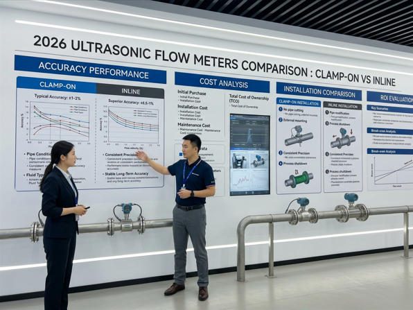
- الدقة: How close each measurement is to the true value. Higher-tier inline multi-path meters achieve ±0.15–0.5%; single-path clamp-on meters typically deliver ±1.0–2.0% under real-world conditions.
- التكرار: The meter’s ability to produce the same reading when measuring identical flow conditions — critical for closed-loop process control.
- Turndown ratio: The operating range over which the meter maintains its specified accuracy. Multi-path inline meters can sustain 400:1 turndown; clamp-on single-path units typically offer 100:1.
Clamp-On Ultrasonic Flow Meters: Overview

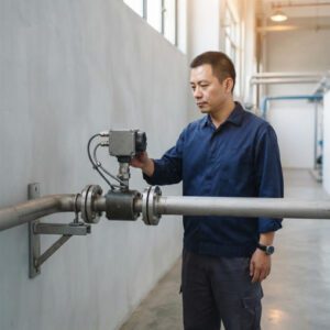
Clamp-on transducers mount on the outside of existing pipe — no cutting, no process shutdown, no contamination risk.
Typical Hardware and Non-Invasive Installation
A clamp-on flow meter system consists of two main components: a transmitter/receiver unit (the electronics box) and a pair of piezoelectric transducers housed in rugged, typically IP67- or IP68-rated enclosures. The transducers are secured to the pipe exterior using mounting fixtures — adjustable rail systems, chains, or adhesive clamps — and are acoustically coupled to the pipe wall using a contact gel or solid-state coupling pad. The entire installation, from unboxing to first live reading, can be completed by one technician in under an hour on a known pipe.
The key inputs the meter needs are pipe outer diameter, wall thickness, and pipe material. These values define the acoustic path geometry. An error of even 1 mm in wall thickness can shift the reading by 2–3% on a DN100 carbon steel pipe — which is why a quick ultrasonic wall-thickness check at the sensor location is always worth doing before committing to a measurement site.
Pros and Limitations of Clamp-On Devices
| الميزة | Practical Impact | Limitation | Practical Impact |
|---|---|---|---|
| No pipe cutting required | Zero process downtime during installation | Sensitive to pipe wall condition | Corrosion, scale, or liners attenuate the signal |
| Zero pressure drop | No pumping energy penalty | Accuracy limited to ±1–2% (single-path) | Not suitable for fiscal or custody-transfer metering |
| Suitable for any pipe material | Works on steel, PVC, copper, HDPE, lined pipes | Requires acoustic couplant maintenance | Gel degrades in 1–2 years outdoors; pads last 5+ years |
| Portable variants available | One kit covers multiple pipe sizes; ideal for audits | Requires full pipe (liquid-filled) | Cannot measure partially filled pipes |
| مجموعة واسعة من أحجام الأنابيب | DN25 to DN6000+ with appropriate transducers | Sensitive to entrained air/solids (transit-time) | Even 1–2% air can cause large measurement errors |
Common Use Cases and Industries
Clamp-on transit-time meters dominate in HVAC energy sub-metering (chilled water, hot water loops), municipal water network monitoring, pharmaceutical utility water systems, clean chemical process monitoring, and food & beverage clean-in-place (CIP) cycle measurement. Their non-invasive nature is particularly valued in pharmaceutical and food applications, where pipe penetration would compromise product purity and trigger costly revalidation procedures.
Portable clamp-on meters serve a different but equally important B2B market: plant energy audits, leak detection surveys, commissioning verification, and meter-versus-meter comparison testing. A single portable unit from a supplier like أدوات النمل اليشم can survey dozens of measurement points across a facility in a single day — generating the data needed to prioritize permanent meter installations with confidence.
Inline (In-Line) Ultrasonic Flow Meters: Overview

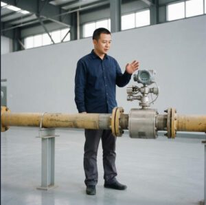
Inline (spool-piece) ultrasonic meters replace a section of pipe and provide the stable, high-accuracy measurement needed for fiscal metering and regulatory compliance.
How Inline Meters Are Installed and Calibrated
An inline ultrasonic flow meter is a pre-fabricated spool piece — a section of precision-bore pipe with transducers integrated directly into the body, either flush-mounted or recessed into ports in the pipe wall. Installation requires the following steps: isolate the process line, drain or depressurize the affected section, cut out the existing pipe, install the spool piece between flanges (or butt-weld for sanitary applications), reconnect the process, and commission the meter by entering fluid properties and verifying the zero-flow reading.
Because the acoustic path is machined into the spool piece at the factory, there is no pipe wall uncertainty, no coupling gel, and no need to measure external pipe dimensions. The geometry of every ultrasonic path is precisely known, which is why inline meters are submitted for wet-flow calibration on a NIST-traceable calibration rig before shipment — delivering a factory-calibrated accuracy certificate that holds up in regulatory and commercial audits. According to KOBOLD USA’s calibration guidance, ISO 17025-accredited and NIST-traceable calibration is the recognized gold standard for industrial flow meters used in fiscal or regulatory applications.
Pros and Limitations of Inline Devices
The primary strengths of inline transit-time meters are their superior accuracy (±0.15–0.5% for multi-path designs), faster response times (as low as 50 milliseconds), and more stable long-term calibration — the acoustic path geometry simply does not change once the meter is installed and bolted between flanges. Multi-path designs (with 4, 5, or more ultrasonic chords) can detect and compensate for swirl and asymmetric flow profiles, making them robust to imperfect upstream conditions.
The trade-offs are significant: installation requires a process shutdown, pipe cutting, and mechanical assembly work that can cost 3–5× the price of the meter itself in retrofit situations. For a DN50 spool piece priced at $4,000, total installed cost in an existing plant can reach $15,000–$20,000 once labor, welding, pipe work, and downtime are factored in. Inline meters also introduce additional pipe joints (flange connections) that create potential leak points — a consideration in hazardous-fluid or high-purity applications.
Typical Applications Where Inline Is Preferred
Inline ultrasonic meters are the technology of choice wherever measurement accuracy has direct financial or legal consequences: oil and gas custody transfer (where a 0.5% error on 100,000 barrels per day can represent $30,000–$50,000 of unaccounted product daily), district energy billing, pharmaceutical batch record documentation (FDA 21 CFR Part 11 compliance), water utility revenue metering, and any application governed by API MPMS Chapter 5.8 or similar custody-transfer standards.
▶ The ultrasonic flow measuring principle — how transit-time and Doppler technologies work, including clamp-on and inline configurations. Credit: Endress+Hauser.
When to Choose Clamp-On vs Inline
Factors Driving the Decision: Pipe Material, Temperature, and Accessibility
The three most immediate field constraints that steer the technology decision are pipe material, operating temperature, and physical accessibility. Clamp-on meters work across almost any pipe material — carbon steel, stainless, copper, PVC, HDPE, cast iron — but perform poorly on pipes with air-gap linings (rubber or PTFE-lined pipe where the liner is not bonded to the wall), heavily corroded walls with wall-thickness variation above 15%, or concrete pipes where signal attenuation is severe. If the target pipe fails any of these conditions, inline insertion or spool-piece meters are the only reliable path to accurate measurement.
Operating temperature matters because acoustic coupling gel has a practical temperature ceiling of around 80–100°C in most formulations. For high-temperature pipes (>120°C), either a high-temperature coupling compound must be used, or the transducer must be moved to a cooler section. Inline meters face no such constraint because the transducer material is selected to match the process temperature at the factory.
Process Requirements: Accuracy, Response Time, and Pressure Drop
The accuracy decision matrix is straightforward when framed in terms of application consequence. If a ±1–2% error has no meaningful impact on your process outcome — consumption trend monitoring, pump performance verification, demand-based ventilation control — then a clamp-on transit-time meter delivers excellent value. If that same ±1–2% error represents thousands of dollars per day in billing discrepancies or regulatory penalties, inline multi-path technology justifies its premium.
Response time is the next differentiator. Batch dosing systems and PID control loops that need to react to flow changes in under 200 milliseconds require inline meters (typical update rate: 50–200 ms). Clamp-on meters typically update every 500–2,000 milliseconds — perfectly adequate for trend monitoring and totalization but too slow for fast closed-loop control. Pressure drop is non-existent for both clamp-on and spool-piece ultrasonic meters, which is why they are preferred over orifice plates and other differential-pressure devices in energy-sensitive applications.
Operational Constraints: Downtime, Maintenance, and Accessibility
Plant operators consistently cite unplanned downtime as their highest-cost maintenance outcome. Clamp-on meters can be installed, repositioned, or replaced without any process interruption — a critical advantage in continuous-process industries like chemicals, paper, and food manufacturing. A failed clamp-on transducer can be replaced in under 15 minutes by one technician without special tools, permits, or process isolation. A failed inline meter typically triggers a maintenance work order, a safety permit, process isolation, pipe draining, and mechanical disassembly — a process that can take days in a congested plant.
Maintenance accessibility also affects the decision for remote or difficult-to-reach measurement points. A clamp-on meter installed on a pipe routed through a ceiling void is far easier to service than an inline meter in the same location that would require scaffolding and pipe work for any intervention.
Key Performance Parameters to Compare
Accuracy, Repeatability, and Turndown Ratio
| المعلمة | Clamp-On Single-Path | Clamp-On Dual-Path | Inline Single-Path | Inline Multi-Path (4–5 paths) |
|---|---|---|---|---|
| Accuracy (% of reading) | ±1.0% – ±2.0% | ±0.5% – ±1.0% | ±0.5% – ±1.0% | ±0.15% – ±0.5% |
| التكرار | ±0.2% – ±0.5% | ±0.15% – ±0.3% | ±0.1% – ±0.2% | ±0.05% – ±0.15% |
| نسبة التخفيض | Up to 100:1 | Up to 150:1 | Up to 200:1 | Up to 400:1 |
| زمن الاستجابة | 0.5 – 2.0 s | 0.3 – 1.0 s | 0.1 – 0.5 s | 0.05 – 0.2 s |
| Pipe Diameter Range | DN25 – DN6000 | DN50 – DN3000 | DN15 – DN1200 | DN50 – DN3000+ |
| Calibration Method | Factory dry-cal; field verification | Factory dry-cal + in-situ check | NIST-traceable wet-flow cal | NIST-traceable wet-flow cal + diagnostics |
| Typical Purchase Price (DN100) | $1,500 – $4,000 | $3,500 – $7,000 | $3,000 – $8,000 | $8,000 – $20,000 |
| Typical Installed Cost (DN100) | $1,500 – $5,000 | $4,000 – $9,000 | $8,000 – $20,000 | $15,000 – $35,000 |
Table 1: Performance and cost comparison. Installed cost includes labor, pipe work, commissioning, and downtime for inline meters. Sources: manufacturer data sheets, BCST Group pricing analysis, and field survey data.
Bar width proportional to typical achievable % error (lower = more accurate). *Clamp-on custody transfer requires in-situ calibration verification. Sources: manufacturer data, API MPMS Ch. 5.8, field study data.
Velocity Range, Flow Range, and Signal Stability
Both meter types cover a wide velocity range — typically 0.01 to 12 m/s for transit-time configurations — but inline meters maintain signal stability more consistently across that range because the acoustic path is fixed and well-defined. Clamp-on meters can experience signal quality variations when flow velocities drop below approximately 0.05 m/s, because the transit-time difference becomes very small relative to the absolute transit time and the signal-to-noise ratio decreases. For low-flow applications — cooling tower bleed, chemical dosing verification, laboratory water supply monitoring — inline meters with their tighter mechanical tolerances provide more reliable readings at the lower end of the range.
Temperature, Pressure, and Media Compatibility
Standard clamp-on meters handle process temperatures from –40°C to +160°C with appropriate transducer and couplant selection. High-temperature versions extend the upper limit to +200–250°C. Inline spool-piece meters can be engineered for higher temperature and pressure ratings with appropriate pressure class flanges and body materials, making them the preferred choice for steam condensate, high-pressure boiler feedwater, and similar demanding thermal environments.
Media compatibility deserves special attention in chemical processing. Clamp-on meters contact only the pipe exterior — they can be used on pipes carrying highly corrosive or toxic fluids without any wetted material concerns. Inline meters must be specified with materials compatible with the process fluid: AISI 316L stainless steel for aggressive chemicals, Hastelloy C for hydrochloric acid service, or PVDF for concentrated oxidizing acids. The ultrasonic meter guide for chemical plants from Jade Ant Instruments provides detailed material compatibility guidance for common process chemicals.
Installation Considerations
Site Survey: Piping Layout and Accessibility
A thorough site survey before ordering either meter type prevents the majority of installation failures. For clamp-on meters, the survey must identify a straight pipe section with at least 10 pipe diameters (10D) of unobstructed run upstream and 5D downstream from the sensor location. The pipe must be full of liquid at all times during measurement — location at the bottom of a riser or just downstream of a pressurized section ensures this. Pipe wall thickness must be measured at four points around the circumference; a variation greater than 10% indicates corrosion that will compromise accuracy. According to Zero Instrument’s installation guide, following these straight-pipe guidelines typically improves measurement accuracy by 30–50% compared to ad-hoc sensor placement.
For inline meters, the site survey focuses on confirming flange-to-flange dimensions match the available spool-piece length, verifying that the pipe section can be isolated and drained, and ensuring lifting equipment access (larger spool pieces for DN300+ can weigh 50–200 kg). ATEX zoning maps must be reviewed if the installation is in a classified hazardous area — this affects both the meter’s certification requirements and the hot-work permits needed for welding or cutting.
Mounting Methods, Coupling, and Alignment
For clamp-on meters, two mounting configurations are used. The V-method (reflect path) places both transducers on the same side of the pipe; the signal bounces off the far wall before reaching the second transducer. This is preferred for smaller pipes (DN25–DN200) where the signal path is short enough for good signal strength. The Z-method (direct path) places transducers on opposite sides; the signal travels diagonally across the pipe diameter. This is preferred for larger pipes and for pipes with attenuating materials (thick walls, lined pipes) where the Z-path offers a stronger signal.
Alignment precision is critical: a 1° angular misalignment of the transducer can shift the effective path length enough to cause a 2–5% measurement error. Quality mounting fixtures with adjustable rail systems maintain alignment integrity over years of operation, including thermal expansion and vibration cycles.
Electrical Wiring, Calibration, and Commissioning
Both meter types require electrical connections for power (typically 24 VDC or 85–265 VAC) and signal output (4–20 mA, pulse, RS-485, or HART). Cable routing must maintain a minimum 300 mm separation from power cables and variable-frequency drives (VFDs) to prevent electromagnetic interference from corrupting signal quality. Conduit or armored cable provides additional protection in electrically noisy environments.
Commissioning verification for clamp-on meters involves checking the meter’s built-in signal quality indicator (typically a Q-value or signal strength percentage — values above 60–80% indicate reliable measurement) and comparing the meter reading against a reference measurement where possible. For inline meters, a factory calibration certificate traceable to NIST or equivalent national standards body should accompany every meter, and an on-site zero-flow check verifies the calibration has not shifted during shipping and installation.
Maintenance, Diagnostics, and Reliability

Modern ultrasonic meters provide real-time self-diagnostics that flag signal quality issues, velocity profile anomalies, and couplant degradation before they cause measurement failure.
Common Failure Modes and Troubleshooting Tips
Neither clamp-on nor inline ultrasonic meters have moving parts, which eliminates the most common cause of mechanical flow meter failure — bearing and impeller wear. The failure modes that do occur are acoustic rather than mechanical, and most can be detected and resolved without replacing hardware.
For clamp-on meters, the three most frequent issues are: (1) coupling degradation — the acoustic gel dries, hardens, or washes away, causing signal quality to drop below the reliable measurement threshold; (2) pipe wall changes — progressive corrosion or scale buildup alters the wall thickness and acoustic properties that the meter was calibrated against; (3) transducer misalignment — thermal expansion or mechanical disturbance has shifted the transducer position, changing the effective path length. All three issues manifest first as declining signal quality metrics, providing early warning before accuracy is significantly affected. For inline meters, the primary failure mode is deposit buildup on transducer windows — typically from scaling, biofilm, or polymerizing process fluids — which attenuates the signal over months or years.
Diagnostics Features: Real-Time Diagnostics and Alarms
Modern ultrasonic meters include extensive self-diagnostic capabilities that go well beyond simple GO/NO-GO readings. High-end meters report signal gain, signal-to-noise ratio, transit-time symmetry (the difference between upstream and downstream signal paths in zero-flow conditions — any asymmetry indicates a potential installation or pipe condition issue), and turbulence indicators derived from the variance in repeated velocity measurements. According to market analysis of the intelligent flow meter segment, IoT-enabled meters with integrated diagnostics and remote monitoring capabilities are growing at 4.9% CAGR through 2030, driven by industrial adoption of predictive maintenance strategies that reduce unplanned downtime by 30–50%.
Digital communication protocols (HART, Modbus, Profibus) allow diagnostic data to be extracted by the plant’s asset management system, enabling trend analysis that catches gradual degradation before it becomes a measurement problem. This is particularly valuable for high-value inline meters where scheduled maintenance access is infrequent.
Calibration Intervals and Field Service Guidelines
Industry best practice for ultrasonic flow meters — both clamp-on and inline — is annual calibration verification. For regulated industries (pharmaceutical, oil and gas custody transfer, utility metering), calibration intervals may be shorter and must be documented. Clamp-on meters are typically verified by comparing readings against a portable reference meter or by performing an in-situ check using the meter’s own diagnostics. Inline meters are either returned to a calibration lab or verified using a portable clamp-on as a check meter applied to the same spool piece location. Smart meters reduce calibration costs by 20-30% through continuous self-diagnostics that can demonstrate measurement stability between formal calibrations, extending justified recalibration intervals for stable installations.
Applications and Industry Use Cases
Water and Wastewater Scenarios
Water and wastewater is the largest application segment for ultrasonic flow meters, accounting for approximately 40–45% of global unit shipments. The two sectors have very different requirements that align neatly with the two technologies. Clean water distribution — municipal mains, district metering areas, building water supply — is almost entirely served by transit-time ultrasonic meters (clamp-on or inline), where the clean, particle-free water provides ideal acoustic transmission conditions. Clamp-on meters are widely used for audit and check metering across large distribution networks, while inline multi-path meters serve as the primary revenue metering devices at district boundaries and pump station discharge points.
Wastewater and sludge handling is Doppler territory: influent flow measurement, return activated sludge, thickened sludge transfer, and digester feed all contain sufficient suspended solids and gas bubbles to sustain Doppler operation. Transit-time vs. Doppler selection for water applications is one of the most common questions from utility engineers, and the answer almost always comes down to a single characterization: is the fluid clean enough for transit-time, or does it contain enough reflectors for Doppler?
Chemical and Petroleum Processes
Chemical and petroleum applications present the widest variety of measurement challenges — from ultra-clean pharmaceutical-grade solvents to viscous crude oils to highly corrosive acids. The common thread across all these applications is the value placed on non-invasive measurement: pipe penetrations in chemical plants are potential leak sources, and every wetted fitting is a potential corrosion point or contamination risk. Clamp-on transit-time meters eliminate these concerns by measuring through the pipe wall, making them standard equipment for monitoring clean chemical feed rates, solvent flows, and cooling water systems in refineries and chemical complexes.
For higher-accuracy needs in petroleum custody transfer and allocation metering, inline multi-path transit-time meters meeting API MPMS Chapter 5.8 are the industry standard. The global ultrasonic flow meter market reached USD 2.08 billion in 2025 and is projected to grow to USD 3.56 billion by 2030 at a 5.1% CAGR, driven significantly by oil and gas custody transfer modernization programs replacing aging turbine and positive displacement meters with multi-path ultrasonic devices that offer better diagnostics and lower maintenance costs. (Fortune Business Insights, 2025)
Food, Beverage, and Pharmaceuticals
These industries have two non-negotiable requirements that make clamp-on ultrasonic meters the dominant technology: no contamination of the product, and no disruption of validated processes. In pharmaceutical manufacturing, any change to wetted piping components (including adding an inline meter) triggers a revalidation process that can take weeks and cost tens of thousands of dollars in engineering time, laboratory testing, and regulatory documentation. A clamp-on meter that measures through the existing validated pipe wall without touching the product simply does not create this burden.
Food and beverage plants face similar contamination concerns: meters in direct product contact must meet 3-A Sanitary Standards, FDA material requirements, and EHEDG guidelines. For utility water and CIP circuit monitoring — where the fluid is cleaning chemical rather than product — clamp-on meters are used extensively for flow verification without any material compliance concerns. For product-contact metering where inline measurement is unavoidable, hygienic spool-piece ultrasonic meters with polished bores, full-bore designs (no dead legs), and FDA-compliant materials meet the sanitary standards required. For detailed information on preventing contamination with ultrasonic flow meters, Fuji Electric’s technical resource provides practical guidance across both food and pharmaceutical application types.
Source: Estimated from Fortune Business Insights, Fact.MR, and Mordor Intelligence ultrasonic flow meter market reports (2025). Market size USD 2.08 billion in 2025.
Cost of Ownership and ROI Considerations
CapEx vs OpEx: Purchase, Installation, and Downtime Costs
The purchase price comparison between clamp-on and inline meters is only part of the total cost story — and often not the most important part. For a retrofit installation on a DN150 process line, a clamp-on meter priced at $3,000 may require $500–$1,500 of labor for installation and commissioning: one technician, half a day’s work, no pipe isolation required. The same measurement point served by an inline spool-piece meter priced at $6,000 may require $8,000–$15,000 of additional costs: pipe cutting, flanging or welding, gaskets, process drain-down, scaffold access, safety permits, process startup, and verification testing. The inline option costs 3–6× more in total, even though the meter itself costs only 2× more.
This CapEx asymmetry reverses in applications where inline measurement is installed during new construction or a planned turnaround. In a greenfield project, the marginal cost of installing an inline spool-piece versus a clamp-on is largely just the meter price difference — labor costs are already accounted for in the piping installation contract. This is why inline meters dominate in new plant construction while clamp-on meters dominate in retrofit and monitoring applications.
Longevity, Maintenance Frequency, and Reliability
Both technologies share the critical advantage of having no moving parts. Mean time between failure (MTBF) figures for quality ultrasonic meters exceed 100,000 hours (over 11 years of continuous operation). The primary ongoing cost for clamp-on meters is couplant maintenance — gel compounds need inspection and refresh every 1–2 years in outdoor or high-temperature environments; solid-state coupling pads can last 5+ years. The primary ongoing cost for inline meters is transducer window inspection in applications with scaling or deposit-forming fluids.
Smart meters with predictive diagnostics can reduce total maintenance costs by 30–50% by shifting from time-based to condition-based maintenance schedules — performing couplant checks and calibration verifications only when the meter’s own diagnostics indicate declining performance rather than on a fixed annual schedule. According to Kytola’s smart flow meter ROI analysis, intelligent meters with self-diagnostic capabilities typically deliver a 12–24 month payback period through maintenance savings and energy optimization alone.
Total Cost of Ownership Examples and ROI Hints
| فئة التكلفة | Clamp-On (10-Year, DN100) | Inline Multi-Path (10-Year, DN100) | Notes |
|---|---|---|---|
| Meter Purchase | $2,500 | $10,000 | Representative mid-range units |
| Installation Labor & Materials | $800 | $12,000 | Inline includes pipe work, downtime costs |
| Commissioning & Initial Calibration | $400 | $1,500 | Inline cal includes NIST-traceable certificate |
| Annual Maintenance (×10 yrs) | $2,000 | $3,000 | Clamp-on: couplant + signal checks; Inline: window inspection |
| Recalibration (×5 cycles) | $2,500 | $5,000 | Inline recal may require meter removal & lab testing |
| Unplanned Downtime Risk (est.) | $500 | $5,000 | Clamp-on failure: replace transducer on-line; Inline: process isolation required |
| Energy / Pressure Drop | $0 | $0 | No pressure drop for either ultrasonic type |
| التكلفة الإجمالية للملكية على مدى 10 سنوات | ~$8,700 | ~$36,500 | Inline TCO is 4.2× clamp-on for retrofit scenarios |
Table 2: Representative 10-year TCO for DN100 retrofit installation. Actual costs vary significantly by site, region, and operational complexity. Compiled from TCO analysis by Titan Flow Meters و industry maintenance cost benchmarks.
How to Select a Supplier and Verify Specifications

Rigorous supplier evaluation — including reference site visits, calibration certificates, and protocol compatibility checks — prevents costly specification mismatches.
Request for Proposal (RFP) Considerations
An effective RFP for ultrasonic flow meters should specify performance requirements rather than brand names. The key technical parameters to include are: required accuracy class (as % of reading, not % of full scale), operating flow range and minimum detectable flow rate, process fluid and its nominal temperature and pressure range, pipe material and diameter, communication protocol requirements, hazardous area classification (if applicable), and environmental ratings (IP class, ambient temperature range). Including these parameters forces suppliers to demonstrate compliance with your actual process needs rather than quoting their best-performing product in ideal laboratory conditions.
Request that suppliers provide a minimum of three reference installations in comparable applications — similar industry, fluid type, and pipe size — with contact information for the reference customer. A supplier confident in their product’s real-world performance will provide these references readily; reluctance to do so is itself informative. Independent manufacturer comparisons can supplement the RFP evaluation by benchmarking multiple suppliers against standardized criteria.
Validation Steps: Reference Installations and Test Data
Before final supplier selection, request the factory calibration certificate with full calibration data at multiple flow points — not just a summary statement that “the meter meets ±0.5% accuracy.” A genuine NIST-traceable calibration certificate from an ISO 17025-accredited laboratory will show calibration data at a minimum of five flow rates spanning the meter’s operating range, a calibration curve, the calibration uncertainty budget, and the calibration facility’s accreditation number. For clamp-on meters, understand that factory calibration verifies the electronic processing accuracy but does not account for installation-specific variables — so a reference comparison test on your actual pipe is the most meaningful validation.
After-Sales Support, Training, and Documentation
The quality of after-sales support is frequently underweighted in initial procurement decisions and heavily weighted in repeat-purchase decisions. Key support criteria include: response time for technical questions (same-day access to an application engineer is valuable), local inventory of spare transducers and electronics, availability of on-site commissioning and training services, documentation quality (commissioning manuals, calibration procedures, hazardous area installation guides), and remote diagnostic support capability. For IIoT-enabled meters, verify that the supplier’s cloud platform or remote monitoring service has a defined service-level agreement and a clear data ownership policy — increasingly important in process industries with strict cybersecurity requirements.
Future-Proofing and Technology Trends
Advances in Sensing Technology and Material Compatibility
The clamp-on ultrasonic flow meter market is projected to grow from USD 3.86 billion by 2035 at a CAGR of 6.43%, driven by three converging forces: wider adoption in emerging-market water infrastructure programs, the oil and gas sector’s transition from mechanical to electronic metering, and the proliferation of IIoT connectivity requirements that make electronic meters with digital outputs a prerequisite for smart factory initiatives. (Spherical Insights, 2025)
On the materials side, new high-temperature piezoelectric ceramic compositions and improved bonding materials are extending the upper temperature limits of clamp-on transducers from around 160°C today toward 300°C in next-generation products — opening applications in steam systems and high-temperature chemical processes that previously required inline meters. Signal processing advances using MEMS-based transducers are improving performance on small pipes below DN25 and on non-metallic pipes where signal attenuation has historically been a challenge.
Smart Diagnostics, Remote Monitoring, and Integration
Digital integration with IoT-enabled monitoring systems has increased by 58% across industrial plants surveyed in 2025, according to market growth data. The next generation of ultrasonic meters does more than report flow rate — they continuously analyze signal characteristics to detect pipe condition changes, predict transducer end-of-life, identify upstream process upsets from flow profile data, and transmit all of this information through secure industrial protocols to plant asset management systems. This shift from meters-as-sensors to meters-as-diagnostic-instruments is changing the value proposition: the measurement accuracy of the meter matters, but so does the richness of diagnostic data it provides for predictive maintenance.
Wireless communication (WirelessHART, ISA100.11a) is gaining ground in locations where cable installation is prohibitively expensive — remote outdoor metering on long distribution mains, meters in confined spaces, and temporary measurement points. Suppliers offering wireless-ready meters with battery backup (providing 5–10 years of operation from a single battery) are capturing share in municipal water networks where cable infrastructure is impractical. Bronkhorst’s technical knowledge base on ultrasonic measurement principles provides detailed background on how these evolving signal processing techniques improve performance.
Standards, Certifications, and Regulatory Alignment
Regulatory requirements are becoming more stringent across all major ultrasonic flow meter applications. In water utilities, national metering codes (OIML R49 in Europe, AWWA C715 in North America) are being updated to address ultrasonic technology’s specific characteristics. In oil and gas, API and AGA standards committees are revising accuracy and diagnostic reporting requirements for fiscal-grade meters to account for IIoT data availability. In pharmaceutical manufacturing, FDA draft guidance on Process Analytical Technology (PAT) increasingly requires real-time flow data with documented calibration traceability for batch manufacturing processes. Selecting meters from suppliers who actively participate in standards development ensures that the technology will remain compliant with emerging regulatory requirements, reducing the risk of costly meter replacement programs when standards are updated.
📖 Glossary of Key Terms
- Transit-Time (TT)
- A measurement principle where the meter measures the difference in travel time between ultrasonic pulses sent upstream and downstream. Works only in clean, particle-free liquids. Example: DN100 water supply pipe, accuracy ±0.5–1.0%.
- Doppler Effect
- The frequency shift of a wave caused by relative motion between the source and the observer. In flow meters, ultrasonic signals reflected off moving particles or bubbles return at a shifted frequency proportional to their velocity. Example: Wastewater with 200 mg/L suspended solids.
- نسبة التخفيض
- The ratio of maximum to minimum measurable flow within specified accuracy. A 100:1 turndown on a 100 m³/h meter means accurate measurement down to 1 m³/h. Higher turndown = wider useful operating range.
- Acoustic Couplant
- A gel, paste, or solid-state elastomer pad applied between a clamp-on transducer face and the pipe surface to eliminate air gaps that would block ultrasonic signal transmission.
- Multi-Path Meter
- An inline ultrasonic meter using 4, 5, or more ultrasonic beams crossing the pipe at different chord positions. Averages velocity across the full flow profile, achieving ±0.15–0.5% accuracy even with distorted flow profiles.
- CapEx / OpEx
- Capital Expenditure (upfront purchase and installation costs) vs. Operating Expenditure (ongoing maintenance, calibration, and energy costs). TCO analysis considers both over the meter’s operational lifetime.
- NIST Traceability
- Calibration traceable to measurement standards maintained by the US National Institute of Standards and Technology (or equivalent national body), providing a documented, unbroken chain of calibration comparisons with stated uncertainties.
- تصنيف IP
- Ingress Protection rating (IEC 60529) indicating resistance to solid particles and liquids. IP67 = dust-tight and immersion to 1 m; IP68 = dust-tight and continuous immersion beyond 1 m.
- V-Method / Z-Method
- Clamp-on transducer mounting configurations. V-method: both transducers on the same pipe side, signal reflects off the far wall (used for smaller pipes). Z-method: transducers on opposite sides, signal crosses directly (used for larger pipes or attenuating materials).
Choosing the Right Ultrasonic Flow Meter for Your Process
The decision between clamp-on and inline ultrasonic flow meters is not a question of which technology is superior in the abstract — it is a question of which technology is the right fit for your specific combination of accuracy requirement, fluid characteristics, installation constraints, and total cost tolerance. Both technologies are mature, reliable, and well-supported by global supply chains and regulatory frameworks. The wrong choice is almost always the result of over-specifying (paying for 0.15% accuracy when ±1.5% is perfectly adequate) or under-specifying (installing a clamp-on where fiscal-grade measurement is legally required).
✅ Final Decision Checklist
- Can the pipe be cut and the process shut down for installation? — If no, clamp-on is the only option regardless of accuracy requirements.
- What accuracy is actually required? — Define this in % of reading, not vaguely as “high accuracy.” If ±1–2% is acceptable, clamp-on delivers substantial cost savings.
- Is the fluid clean (particle-free, gas-free)? — If yes, transit-time. If it contains particles or bubbles, Doppler. If it alternates, consult a specialist.
- What communication protocol does your control system use? — Verify the meter natively supports it; avoid protocol converter dependencies.
- What does the total installed cost look like over 10 years? — Include installation labor, downtime, recalibration, and replacement risk in the comparison.
- Has a site survey confirmed adequate straight pipe runs? — Both technologies need 10D upstream / 5D downstream; verify this before specifying.
- Have you requested reference installations in comparable applications? — Real-world performance data from similar processes is more reliable than catalog accuracy specifications.
The engineering team at أدوات النمل اليشم works with B2B procurement specialists and plant engineers to navigate exactly these decisions — matching the right ultrasonic meter technology to the realities of each measurement point rather than pushing a catalog default. Whether your project involves a single retrofit measurement point or a multi-site instrumentation program across an entire facility, structured technical evaluation at the selection stage prevents the expensive corrections that come from mismatched specifications. For further reading on how to approach the broader flow meter selection decision, this 5-factor selection framework provides a practical starting point.
Need Help Specifying the Right Ultrasonic Flow Meter?
Jade Ant Instruments provides application engineering support, technical data sheets, and competitive quotations for clamp-on and inline ultrasonic meters across all major industrial sectors.
Explore Our Flow Meter Range →
In large-scale industrial facilities, a combination of clamp-on (for monitoring) and inline multi-path (for fiscal metering) ultrasonic meters provides the optimal balance of coverage, accuracy, and total cost of ownership.