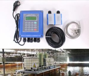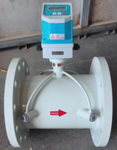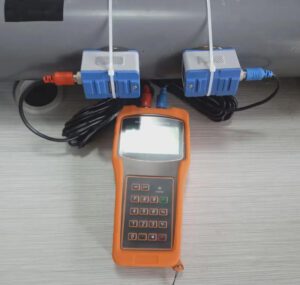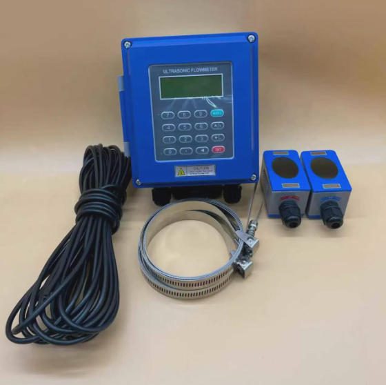

A permanent clamp-on installation on a DN300 steel process header — no pipe cutting, no shutdown, commissioned in under two hours.
The global clamp-on ultrasonic flow meter market was valued at USD 1.13 billion in 2025 ومن المتوقع أن يصل إلى USD 2.21 billion by 2034, growing at 7.8% per year — the fastest growth segment in the entire flow measurement industry. That number is not driven by marketing momentum. It is driven by a hard operational reality: at most industrial facilities, the biggest cost in adding a flow measurement point is not the meter itself — it is the pipe cutting, the shutdown, the hot-work permit, the weld inspection, and the production loss that traditional inline installation requires. Clamp-on eliminates every one of those costs, and industry is responding accordingly.
But the non-invasive installation advantage is only meaningful when the meter is correctly matched to the application. The wrong meter — a single-path transit-time unit on aerated wastewater, a standard IP67 transmitter in a daily CIP steam environment, an ±2% meter on a district energy billing header — delivers readings that drift, fail calibration, or stop working entirely within months. Every one of those outcomes is a specification error, not a hardware failure, and every one of them happens before the meter ever leaves the warehouse.
تم إعداد هذا الدليل خصيصًا لـ OEM equipment and skid-mount manufacturers, instrument distributors and importers, EPC and system integrators, industrial terminal and MRO companies, and municipal and utility operators — the professionals who specify, supply, and maintain these systems in real environments. It covers the complete decision path from application definition through vendor selection, with the specific data and field context that turns a specification decision into a defensible recommendation.
Before looking at a single datasheet, the most important step is defining what the measurement is actually supposed to do — because the answer determines which technologies are viable and which are not, often before accuracy or pipe material even enter the conversation.
Custody transfer — measurement that triggers a financial transaction — sits at the top of the requirement hierarchy. When a district cooling provider bills a commercial building tenant based on chilled water flow, or when a water utility invoices an industrial customer for consumption, that measurement must be traceable, documented, and auditable. Custody transfer demands the highest accuracy tier, calibration certificates traceable to national standards, and compliance with applicable standards such as EN 1434 (heat metering, Class 2) or OIML R 49 (potable water billing meters). This level of requirement constrains technology choices significantly. High-accuracy dual-path clamp-on meters with in-situ verification capability do meet EN 1434 Class 2 requirements in water and district energy applications — but fiscal custody transfer for natural gas (AGA-9) and liquid hydrocarbons (API MPMS Chapter 5.8) still requires certified inline multi-path meters. Understanding this boundary prevents an expensive post-delivery dispute.
Process control applications — where the flow signal feeds back into a valve position, pump speed, or dosing controller in real time — demand fast response and high repeatability more than absolute accuracy. A meter that consistently reads 1.2% high is workable if that offset is stable; a meter that drifts unpredictably between 0.5% and 3% makes the control loop hunt. For these applications, response time (how quickly the meter updates its output after a flow change), signal stability, and turndown ratio matter more than the headline accuracy percentage on the datasheet.
Energy monitoring, system balance, and loss detection — the most common application category for permanent clamp-on installations — has the most relaxed accuracy requirement. Here, ±1–2% is almost always sufficient, which opens the full range of transit-time clamp-on options. This is also where the non-invasive installation advantage is most commercially compelling: a utility company deploying 200 check meters across a distribution network at 60-minute SCADA polling intervals gains far more operational value from having all 200 points instrumented at ±1.5% than from having 40 points at ±0.3% and the rest unmetered because the budget ran out after inline installation costs.
Maintenance and commissioning verification is where portable clamp-on kits are indispensable. A single portable kit with three transducer sets covering DN50 to DN600 replaces what would otherwise require multiple fixed instruments across different pipe sizes — and it can verify system performance, troubleshoot an anomaly, or audit an existing meter without interrupting the process.
Fluid type is the next critical filter. Clean liquids — treated water, glycol solutions, pharmaceutical purified water, food-grade fluids, most industrial chemicals — are ideal for transit-time measurement, the dominant clamp-on technology. Two transducers send ultrasonic pulses upstream and downstream alternately; the tiny travel-time difference reveals fluid velocity. Dirty or aerated liquids — raw sewage, activated sludge, slurries, liquids with entrained air — require Doppler measurement, which bounces signals off suspended particles or bubbles. These are not interchangeable. Installing a standard transit-time meter on a raw wastewater line produces no signal at all, not a degraded reading — the suspended solids scatter the acoustic pulse completely.
Flow variability shapes the required turndown ratio — the ratio of maximum to minimum measurable flow at which the meter maintains its specified accuracy. A process that runs at 5% of design capacity during nights and 95% during peak production needs a meter that is accurate across that entire range. Quality transit-time clamp-on meters achieve 100:1 to 150:1 turndown. Turbine meters typically manage 10:1. For variable-load systems — HVAC plants, water distribution mains, batch process lines — this specification alone often justifies the technology choice.
Once the application purpose, fluid type, and flow range are defined, accuracy becomes a concrete number rather than a comparative ranking. ±0.5% من القراءة represents the upper boundary for clamp-on technology, achievable with dual-path configurations on well-characterised pipe, adequate straight run, and in-situ calibration verification. This level is appropriate for district energy billing, sub-metering in tenant billing, and high-value chemical process lines where even a 1% feed-rate error represents significant material cost. ±1.0% of reading is the standard performance of a quality single-path clamp-on meter under good installation conditions — proper pipe parameters entered, quality couplant, stable fluid. An independent field study confirmed this as the realistic best-case field accuracy for most installations under real-world conditions, not lab environments. ±2.0% is the realistic performance on a non-ideal installation: short straight run, scaled pipe interior, fluid near the limits of transit-time measurement. For general process monitoring where this tolerance is acceptable, a ±2% meter at lower cost is a better commercial outcome than a ±0.5% meter over-specified for a non-critical point.
The financial implication of accuracy is the argument that moves buyers. A DN300 chilled water header carrying 800 m³/h with a 6°C supply/return temperature differential represents roughly 5.6 MW of cooling load. At a district cooling tariff of $0.08/kWh, a 2% metering error generates approximately $78,000 in annual billing discrepancy. The cost difference between a ±2% single-path and a ±1% dual-path meter at that application is $2,000–$3,000. The upgrade pays back in under two weeks of correct billing. This is the calculation that turns an accuracy specification from a technical footnote into a financial decision.
| نوع التطبيق | Required Accuracy | Recommended Configuration |
|---|---|---|
| General process monitoring | ±1.0–2.0% | Single-path clamp-on |
| HVAC / energy sub-metering | ±1.0% | Single-path + temperature sensors |
| District energy billing (EN 1434 Class 2) | ±1.0% | Dual-path + dual RTDs |
| Revenue metering / DMA inlet | ±0.5–1.0% | Dual-path + in-situ verification |
| Fiscal custody transfer (gas / hydrocarbons) | ±0.15–0.25% | Inline multi-path (AGA-9 / API MPMS) |
| Portable commissioning audit | ±1.0–2.0% | Portable clamp-on kit |
With the accuracy requirement defined, the pipe is the next variable — and the one most frequently underestimated. Clamp-on meters transmit ultrasonic energy through the pipe wall before it reaches the fluid, which means the pipe is part of the measurement system. Its material, condition, diameter, and wall thickness directly determine whether the meter can measure reliably and which transducer and mounting configuration to use.
Compatible pipe materials are broad: carbon steel, stainless steel (304, 316, duplex grades), copper, brass, ductile iron, PVC, CPVC, HDPE, PP, and PVDF all transmit ultrasonic energy with manageable attenuation when the surface is clean and wall thickness is uniform. Problematic conditions are specific and important to screen for before purchase. Internally rubber-lined pipe creates an air gap between the rubber and the steel body that acts as near-total acoustic reflection — clamp-on meters cannot see through it. Bitumen and coal-tar internal coatings behave similarly. Heavy internal scale or corrosion above 10 mm introduces acoustic attenuation and wall-thickness uncertainty that degrades signal quality. Concrete-lined pipe has high acoustic attenuation that generally prevents reliable clamp-on measurement without specialized transducers designed for the purpose. A quick check with an ultrasonic wall-thickness gauge at the planned mounting location before purchase — taking approximately five minutes — confirms whether the pipe is suitable and what the actual wall thickness is, which is essential for accurate transducer spacing calculation.
For plastic and non-metallic pipes, coupling sensitivity is higher than on steel. Every trace of paint, grease, rust, or surface contamination between the transducer face and the pipe wall must be removed. High-performance acoustic couplant — applied in a consistent thin layer with no air gaps — is the difference between a stable measurement and an intermittent one. Non-metallic pipes typically require higher-frequency transducers (2–4 MHz) than steel pipe of equivalent diameter, and Z-path mounting (transducers on opposite sides) is usually preferable to V-path on plastic pipe above DN200.
Pipe diameter determines which transducer kit applies. Standard clamp-on systems cover DN25 to DN3000 across multiple transducer sets. Always measure actual outside diameter (OD) with a tape or calipers — do not rely on nominal pipe size. Actual OD varies between pipe schedules and manufacturers; a 1 mm OD error on a DN100 pipe introduces approximately 2% velocity offset before any other error source is counted. For large-bore pipes (DN600 and above), this is the specification check that routinely catches mismatches between the pipe schedule the customer thinks they have and what is actually in the ground.
Minimum straight pipe run is the most consistently underestimated installation constraint. The standard requirement is 10 pipe diameters (10D) of undisturbed straight pipe upstream and 5D downstream of the measurement location. After an elbow, pump outlet, partially open valve, or sudden diameter change, allow 15–20D upstream. Short straight runs produce asymmetric velocity profiles that single-path meters cannot correct for, creating systematic positive or negative offset that looks like poor accuracy but is entirely an installation issue. Where adequate straight run is genuinely unavailable, dual-path meters with velocity profile correction algorithms provide partial compensation — but a portable field survey of the actual velocity profile asymmetry at the intended location is the only reliable way to quantify the remaining error before committing to a permanent installation.
The transducer and its mounting method form the physical interface between the electronics and the pipe. Selecting correctly here determines both measurement quality and long-term reliability.
Non-wetted (clamp-on) transducers mount on the pipe exterior, never contacting the process fluid. This is the standard for corrosive media, food-grade applications, hazardous fluids, and any situation where the pipe must not be penetrated. It is also what enables live installation without any process shutdown. Wetted (insertion-style) transducers penetrate the pipe wall and make direct fluid contact — they offer better signal on difficult pipe materials but require a process tap and isolation valve and cannot be installed on a live, pressurized line. For any application where clamp-on acoustic coupling is feasible, non-wetted transducers are the right choice for commercial and operational reasons.
The mounting geometry — how the acoustic signal path travels through the pipe — depends on pipe size, wall material, and signal strength. V-method (reflect path) places both transducers on the same side of the pipe; the signal reflects off the opposite wall at an angle. This is the standard for most applications on pipes between DN50 and DN600 in good condition. It gives two acoustic passes through the fluid (downstream and upstream after reflection), improving measurement averaging. It requires adequate signal penetration through the pipe wall and back, which is why it struggles on thick-walled plastic, heavily scaled, or lined pipe. Z-method (direct path) places transducers on opposite sides, sending the signal straight across the diameter in one pass. This is correct for large diameters (DN300 and above), acoustically attenuating materials like HDPE and PVDF, pipes with heavy internal scale, and any case where V-method produces insufficient signal strength. The trade-off is that access to both sides of the pipe simultaneously is required. W-method (double reflect path) bounces the signal off the opposite wall twice — three total acoustic passes. Used exclusively on very small pipes (DN15 to DN50) where V-method path length is insufficient for accurate timing. W-method is the most sensitive to installation alignment errors and should only be used where V and Z are not viable.
| حجم الأنبوب | Recommended Method | Typical Application |
|---|---|---|
| DN15–DN50 | W-Method | Small-bore chemical or laboratory lines |
| DN50–DN300 (standard steel) | V-Method | HVAC, water distribution, process lines |
| DN300+ (large bore) | Z-Method | Transmission mains, large process headers |
| Any size — lined or plastic pipe | Z-Method | HDPE, rubber-lined, or heavily scaled pipe |
| DN300+ with high attenuation | Dual-path Z | Large-bore mains with scale or coating |
Mounting hardware in vibration-prone environments deserves specific attention on any quote that includes pump headers, compressor outlets, or lines subject to mechanical shock. Transducers that work loose on a vibrating surface gradually lose acoustic coupling, producing slow reading drift that takes weeks to become visible in trend data. Stainless steel mounting chains or locking bands resist vibration far better than cable ties. For outdoor installations, UV-resistant mounting straps and weatherproof couplant pads outlast gel-based couplants that dry out and crack within months of direct sun exposure.
A meter that tells you only what the flow rate is gives you half the information you need in the field. A meter that also tells you how confident to be in that reading, in real time, is a tool that meaningfully improves operations for everyone from system integrators to MRO teams.
الـ Signal Quality Index (SQI) — expressed as a percentage from 0 to 100% — is the most important real-time diagnostic on any clamp-on transmitter. It reflects how cleanly the acoustic signal is received: signal strength, travel-time consistency, and noise level relative to signal. SQI above 60% indicates reliable measurement. Between 50–60% is marginal — investigate before signing off on a permanent installation. Below 50% means the mounting location or configuration has a problem that must be resolved before the reading can be trusted. This one number answers the question every utility engineer eventually asks: “How do I know it’s actually working?” A declining SQI trend detected in SCADA over weeks or months is an early warning of couplant degradation, surface corrosion developing under the transducer, or fluid condition change — detectable and correctable before it crosses into measurement failure.
Velocity of sound (VoS) monitoring is the second key diagnostic. The meter continuously calculates the acoustic speed through the fluid from transit-time measurements. Water at 20°C produces approximately 1,480 m/s; at 80°C it rises to roughly 1,555 m/s. If the measured VoS matches the expected value for the fluid type and temperature, the measurement physics are working correctly. An unexpected VoS deviation signals either a fluid composition change or an incorrect configuration parameter — both requiring investigation before the reading is trusted.
Flow profile diagnostics on dual-path meters compare velocity measured along each acoustic path. Symmetric profiles indicate undisturbed flow and accurate averaging. Asymmetric profiles — where one path reads significantly higher than the other — point to flow disturbance from a nearby elbow, a partially open valve, or non-uniform scale accumulation. This distinguishes between a meter problem and an installation problem without physically inspecting the pipe — which, across a fleet of 50 or 100 remote meters, is the difference between a targeted site visit and a full inspection round. One MRO manager at a water utility managing 80 permanent clamp-on installations reported reducing field inspection hours by approximately 40% after enabling SQI trending in their SCADA historian — because 60–70% of sites consistently showed healthy readings that required no on-site intervention between formal calibration events.
For EPC commissioning teams, diagnostic capability shortens sign-off time directly. A meter with real-time SQI, VoS, and profile diagnostics tells the installation technician within minutes whether mounting location, transducer spacing, and couplant application are correct. Errors are caught and corrected before the commissioning certificate is signed. Meters with HART diagnostic output allow all registers to be read with a standard HART communicator before handover — generating a documented commissioning record with under 30 minutes of additional work per instrument.
The measurement means nothing if it cannot reach the system that acts on it. Output protocol compatibility is where projects get delayed and finger-pointing begins — and where a well-prepared specification prevents all of it.
4–20 mA analog output is the universal baseline, compatible with every PLC, DCS, and SCADA input card manufactured in the last 40 years. It is the safest fallback when the end-user’s control system is legacy or undefined. Configure the scale to represent flow rate (4 mA at zero flow, 20 mA at maximum), add a pulse output for volume totalization, and the meter integrates with virtually any industrial control platform without a protocol converter. إخراج النبض/التردد provides discrete pulses representing incremental volume — standard for batch totalizers, water billing data loggers, and heat meter integrators where accumulated volume is the primary requirement. HART overlays digital communication on the existing 4–20 mA wire, enabling two-way data exchange — reading diagnostics, changing configuration, and generating transmitter health reports — without new cabling. This is the most cost-effective path to smart device management in brownfield installations where rewiring is expensive. Modbus RTU (RS-485) and Modbus TCP (Ethernet) are the dominant protocols for modern SCADA integration. Every major current PLC and SCADA platform — Siemens S7, Allen-Bradley ControlLogix, Schneider Modicon, Inductive Automation Ignition — supports native Modbus drivers. A Modbus-connected meter can report not just flow rate but SQI, VoS, temperature, totalizer value, and alarm status in a single register map read. BACnet MS/TP is the protocol of choice for commercial and institutional building management systems — specify this for clamp-on meters installed in HVAC chilled water loops, district cooling substations, and tenant sub-metering applications where the control system is a Siemens Desigo, Honeywell Niagara, or Johnson Controls Metasys platform. بروفيبوس DP appears in Siemens-dominated process automation environments built through the 2000s and 2010s. Ethernet/IP is the native protocol for Allen-Bradley ControlLogix environments, enabling direct integration from the skid PLC without a gateway.
For OEM skid builders, the practical rule is simple: confirm the end-user’s PLC brand and model before specifying the output protocol. Changing output protocols after delivery requires either a firmware update (if supported) or a meter swap — either of which is an avoidable cost. Embed this question in the order intake checklist. For EPC teams designing multi-vendor skids, standardizing on Modbus TCP as the common instrument protocol and aggregating meter data through a single gateway before the plant DCS connection insulates the project from vendor-specific protocol changes and simplifies I/O tag mapping on handover.
For a comprehensive breakdown of industrial communication protocol options — including register mapping guidance and gateway selection for legacy Profibus and Foundation Fieldbus systems — Turbines Incorporated’s flowmeter communication protocols guide is a technically detailed reference.
Where the meter is installed determines what it must survive over its operating life. Ingress protection, temperature range, and hazardous area classification are not fine-print details — they determine whether the instrument survives its environment for 10 years or fails in 10 months.
IP67 protects against complete dust ingress and submersion in up to 1 meter of water for 30 minutes. Adequate for most covered industrial installations, indoor pump rooms, and outdoor locations not subject to direct flooding or high-pressure cleaning. IP68 extends to continuous submersion at a manufacturer-specified depth — commonly 3 meters. Required for permanently submerged sensor applications, underground meter chambers with regular flood exposure, and direct-burial transducer configurations in water network monitoring. Jade Ant Instruments’ clamp-on sensor housings are rated to IP68, maintaining acoustic coupling integrity from –40°C to +200°C, which covers both Arctic pipeline monitoring at the cold extreme and high-temperature process fluid applications at the hot extreme. IP69K is the highest rating — full dust protection plus resistance to 80°C, high-pressure steam jets at 8–10 MPa applied at close range. This is mandatory for food and beverage, dairy, and pharmaceutical manufacturing environments where CIP (Clean-in-Place) or SIP (Sterilize-in-Place) cleaning applies pressurized steam directly to installed equipment. A standard IP67 transmitter in an IP69K cleaning environment fails seal integrity within months — not years.
Temperature rating applies independently to the sensor and the transmitter. Most standard sensor kits operate on pipe surfaces from –40°C to +100°C, with high-temperature variants extending to +160°C or +200°C. Transmitter electronics are typically rated for –20°C to +60°C ambient. When pipe surface temperature exceeds 80°C, a remote-mount transmitter configuration — sensor connected to electronics via armored signal cable up to 30–50 meters long — is the correct specification, keeping the electronics in a cooler, accessible location while the sensor handles the thermal load at the pipe surface.
For installations in hazardous areas classified as Zone 1 or Zone 2 (flammable gas or vapor atmospheres per IEC 60079), the transmitter, sensors, and all associated cables must carry ATEX certification for European projects or IECEx certification for international applications. The ATEX nameplate marking — for example, II 2G Ex d IIB T4 — encodes the equipment category (2G = Zone 1 rated), gas group (IIB = hydrogen and ethylene range), and temperature class (T4 = max surface temperature 135°C). This marking must be matched against the site’s area classification drawing, not a general project description. For North American installations in Class I Division 1 or Division 2 locations, UL or FM certification per NEC Article 500 applies. Class I Div 2 is available on most manufacturers’ clamp-on models; Div 1 requires product-specific confirmation. ATEX and FM certifications are not interchangeable across regions — confirm the applicable regional scheme for each project country before purchasing.

IP68-rated, ATEX-certified clamp-on sensors on a Zone 2 classified chemical process line — no pipe penetration required even in hazardous environments.
For utility companies, MRO teams, and facility operators managing flow measurement across multiple sites, the meter’s data handling and connectivity capability matters as much as its measurement performance. A highly accurate reading that cannot be trended, remotely accessed, or integrated into an asset management platform delivers a fraction of its potential operational value.
Most permanent clamp-on transmitters include internal non-volatile data logging — recording flow rate, total volume, temperature, and diagnostics at configurable intervals (typically 15 minutes to 1 hour) for 30 to 365 days of historical storage. This internal log is the safety net when SCADA communication is intermittent, providing a continuous measurement record for billing audits or process quality documentation even during communication outages. For MRO technicians conducting site audits, a transmitter with robust internal logging allows download of a full operational history in a single visit — revealing intermittent flow anomalies, signal quality events, or temperature excursions that only a point-in-time field visit would miss entirely.
The most significant recent development in the clamp-on market is native integration of 4G/LTE, NB-IoT, LoRaWAN, and Wi-Fi into transmitter platforms, enabling remote monitoring of sites where wired SCADA infrastructure is impractical or cost-prohibitive. A rural pump station, a remote distribution line monitoring point, or an isolated district energy substation that previously required a $20,000–$50,000 dedicated telemetry infrastructure can now be instrumented with a cellular-connected clamp-on meter for $4,000–$8,000 total installed cost, publishing data to a cloud dashboard accessible from any browser. For municipal utilities managing hundreds of distributed assets, this changes the economics of comprehensive network metering from a 20-year capital programme into a rolling operational deployment. Battery-powered variants with cellular connectivity achieve 3–7 years of autonomous operation at 15-minute reporting intervals — meaningful for remote locations where AC power is unavailable.
For OEMs building connected skid systems and EPCs designing new facilities, OPC UA connectivity in modern transmitters enables direct integration with digital twin platforms, SCADA historians (Aveva PI System, Inductive Automation Ignition, AVEVA Wonderware), and cloud analytics environments (Microsoft Azure IoT Hub, AWS IoT Core). The flow meter becomes an active data node in the facility’s digital infrastructure — contributing to predictive maintenance models, energy optimization algorithms, and production reporting without additional middleware.
Below is a practical video walkthrough of how clamp-on ultrasonic meters work, how to set up transducers, and how to interpret the commissioning diagnostics — recommended for technical sales teams, procurement staff, and anyone new to the technology before their first field installation.
 ▶ Click to watch: How to Install and Use a Clamp-On Ultrasonic Flow Meter — Step-by-Step Guide (YouTube)
Purchase price is the number that appears in a procurement spreadsheet. Total cost of ownership is the number that determines whether the project was actually good value — and for clamp-on technology, the gap between these two figures is wider than for almost any other instrumentation category, consistently in the buyer’s favor.
The most immediate advantage is installation cost. A single instrument technician installs a clamp-on meter — surface preparation, transducer spacing calculation, mounting, couplant application, parameter entry, SQI verification, and output loop check — in 60 to 90 minutes. The same measurement point with an inline spool-piece meter requires a piping contractor crew for pipe cutting and flange welding (4–8 hours), an instrument technician for commissioning (2–3 hours), and a QA inspector for pressure testing (1–2 hours). That is $200–$400 in labor versus $1,500–$5,000 or more per point, before counting process shutdown. For production facilities generating $30,000–$80,000 per hour of output, a 4-hour installation window represents $120,000–$320,000 in opportunity cost — absorbed as real production loss, not estimated inconvenience. Clamp-on avoids this entirely.
| عنصر التكلفة | Clamp-On Meter | Inline Spool-Piece | Saving |
|---|---|---|---|
| Meter purchase price | $1,500–$4,000 | $3,000–$8,000 | $1,500–$4,000 |
| Installation labor | $150–$400 | $1,200–$3,500 | $1,050–$3,100 |
| Pipe cutting and flanging | $0 | $600–$2,000 | $600–$2,000 |
| Process shutdown cost | $0 | $2,000–$15,000+ | Up to $15,000+ |
| Pressure testing and sign-off | $0 | $200–$800 | $200–$800 |
| Commissioning | $100–$300 | $300–$800 | $200–$500 |
| Total installed cost | ~$1,750–$4,700 | ~$7,300–$30,100 | Up to 85% lower |
Illustrative values for a typical brownfield DN100 installation in an operating industrial plant.
Over a 5-year horizon, the operational maintenance difference compounds the initial installation saving further. Clamp-on transducer replacement — the only physical maintenance intervention — takes 20 minutes and does not require stopping the process. A replacement transducer pair costs $200–$500. Replacing an inline meter requires pipe isolation, drain-down, flange bolt removal, spool extraction, installation of the replacement unit, pressure testing, and process restart — a half-day to full-day event generating maintenance orders, hot-work permits, and production loss documentation, typically $2,000–$8,000 in total event cost. Calibration intervals for clamp-on meters in stable, clean-fluid applications are typically 3-5 سنوات with regular SQI monitoring, versus 12–24 months for mechanically wearing inline meters. In-situ verification — using a portable reference meter clamped at the same location — provides a traceable calibration check between formal events at a fraction of removal-and-lab cost.
5-Year Total Cost of Ownership — Clamp-On vs. Inline (Illustrative, DN100 brownfield)
Clamp-On Inline
──────────────────────────────────────────────── Equipment purchase $2,200 $5,500 Installation + shutdown $300 $8,000 Maintenance over 5 years $300 $1,500 Calibration (2 events) $400 $1,000 Downtime for maintenance $0 $2,500 ──────────────────────────────────────────────── 5-Year TCO ~$3,200 ~$18,500
For distributors quoting against lower-priced alternatives, the TCO calculation is the most effective tool in the sales process. Build it with the customer’s own production value per hour, contractor labor rates, and calibration costs — present it on one page — and the meter price becomes a secondary conversation. The customer who has calculated their own 5-year exposure number is not asking which meter is cheapest; they are asking which supplier can help them control the number they just wrote down.
The supplier behind the meter determines whether a field problem becomes a solved problem or a disputed warranty claim. Technical depth, calibration capability, response speed, and long-term product continuity are as much part of the value proposition as any specification on the datasheet.
The most revealing evaluation question is not “what does your meter do?” — it is “can you solve this specific application problem?” Give a prospective supplier a real scenario: a DN400 HDPE pipe carrying cooling tower return water at 35°C with 8 meters of straight run upstream of a 90° elbow. Ask which transducer kit, which mounting method, what accuracy they expect, and what diagnostics confirm the installation is correct. A supplier with genuine application engineering depth answers this with specific technical reasoning. A supplier without it refers you to the datasheet. The answer tells you more about the post-sale relationship than any warranty term.
For OEM skid builders integrating meters into packaged equipment destined for varied end-user environments, supplier technical support during product qualification — reviewing installation drawings for each application, providing custom pipe dimension calculations, confirming transducer spacing for non-standard pipe schedules — is the service that prevents field problems before they leave the factory. Request this specifically and observe the response. Calibration traceability matters equally: for any ISO 9001 environment, pharmaceutical project, or food safety application, factory calibration certificates must be traceable to national standards with the reference standard identified, calibration points documented, and uncertainty calculated at each point. The certificate number enables third-party audit trail without pulling the meter from service.
Warranty terms of 12–24 months are standard, but the questions worth asking are more specific: Is the transducer couplant interface covered? Is the transmitter display covered for UV degradation on outdoor installations? Are firmware updates included, and for how long? A transmitter platform that receives regular firmware updates — adding protocol support, improving signal processing algorithms, extending compensation range — has meaningfully longer operational life than one frozen at the original release. For meters integrated into cloud reporting or SCADA historian systems, firmware update policy directly affects how long the meter can remain a compatible data node in an evolving digital infrastructure.
أدوات النمل اليشم supplies clamp-on ultrasonic flow meters from DN32 to DN1000 in permanent configuration and portable audit kits, with pre-sales application engineering support, ISO 9001-certified factory calibration, CE documentation, and OEM private-label manufacturing for distributor and skid-builder partners. Their clamp-on flow meter non-invasive guide covers the full technology, installation, and application landscape in detail. For distributors evaluating how clamp-on fits against other technologies in a broader portfolio, the clamp-on vs. inline ultrasonic flow meter comparison و leading flow meter manufacturers comparison map supplier capabilities and technology positioning across all major categories.
For general technology selection across ultrasonic, electromagnetic, and turbine technologies — including when each outperforms the others on a specific fluid type or application — Icon Process Controls’ clamp-on flow meter application guide is a well-structured independent reference.

A portable clamp-on audit meter verifying an existing permanent installation — no isolation, no downtime, verification completed in under 20 minutes.
Global Clamp-On Application Distribution by Sector (2025)
CLAMP-ON ULTRASONIC FLOW METER — DEPLOYMENT BY INDUSTRY SECTOR
Water & Wastewater Treatment ████████████████████████████████████ 35% HVAC & District Energy ████████████████████ 20% Chemical & Petrochemical ██████████████████ 18% Oil & Gas (check-metering) ███████████████ 15% Food, Beverage & Pharma ███████ 7% Other Industrial █████ 5%
Source: Fortune Business Insights 2025, DataIntelo 2025
Key Terms Explained
Transit-Time Measurement: Sends paired ultrasonic pulses upstream and downstream; the travel-time difference reveals velocity. Works on clean, particle-free fluids. Typical accuracy: ±0.5–1.0%.
Doppler-Shift Measurement: Measures the frequency shift of signals reflected from particles or bubbles. Works on dirty, aerated, or slurry-laden fluids. Typical accuracy: ±2–5%.
Signal Quality Index (SQI): A real-time 0–100% indicator of received ultrasonic signal strength and consistency. The primary commissioning and health-monitoring diagnostic. Above 60% = reliable; below 50% = investigate.
Velocity of Sound (VoS): The speed of ultrasonic pulses through the process fluid. Varies with fluid type and temperature. Monitored continuously as a fluid identity check. Water at 20°C ≈ 1,480 m/s.
Turndown Ratio: Maximum to minimum measurable flow at specified accuracy. A 100:1 turndown means a meter rated to 10 m/s maximum reliably measures down to 0.1 m/s.
EN 1434 / OIML R 49: EN 1434 defines accuracy classes for heat meters; OIML R 49 governs water meter accuracy classes for utility billing. Both can be met by dual-path clamp-on meters under compliant installation conditions.
Total Cost of Ownership (TCO): Full cost over operating life: equipment + installation + calibration + maintenance + downtime + eventual replacement. The metric that consistently favors clamp-on over inline in brownfield applications.
ATEX / IECEx: ATEX is the European certification scheme for equipment used in potentially explosive atmospheres. IECEx is the international equivalent. Both define zone ratings, gas groups, and temperature classes. Not interchangeable across regions.

Stainless steel mounting straps and high-performance couplant pads — the two installation details most responsible for long-term signal quality in vibration-prone or outdoor environments.
الأسئلة المتداولة
What is the typical accuracy of a clamp-on ultrasonic flow meter?
Most industrial-grade transit-time clamp-on meters achieve ±1.0% of reading under good installation conditions — correct pipe parameters entered, quality couplant, adequate straight run, stable fluid. Dual-path configurations on well-characterised pipe achieve ±0.5%. Doppler meters for dirty fluids typically achieve ±2–5% of full scale. Accuracy depends heavily on installation quality: a correctly installed ±1.0% meter consistently outperforms a poorly installed ±0.5% specification in real-world conditions.
Can clamp-on meters measure dirty or aerated liquids?
Yes, with the right technology. Doppler clamp-on meters are designed specifically for fluids with suspended solids (minimum ~80 mg/L at particle sizes above 75 μm) or significant entrained air. Standard transit-time meters are not suitable for heavily particulate or aerated fluids — the solids scatter the acoustic signal, reducing or eliminating the received reading entirely. For borderline cases, a portable transit-time field test with SQI monitoring at the actual installation location determines signal adequacy before purchase.
Do I need to cut into the pipe to install a clamp-on meter?
No. This is the defining operational advantage. Transducers mount on the outside pipe surface held by stainless steel straps or chains. The pipe wall is never penetrated, no isolation valve is needed, and installation can be performed on a live, pressurized, flowing line during normal operation. Standard DN100 installation takes one technician approximately 60–90 minutes.
How do pipe linings or internal scale affect measurement?
Rubber, bitumen, and coal-tar internal linings create an air-gap acoustic barrier that clamp-on meters cannot penetrate — internally rubber-lined pipe requires an insertion probe or electromagnetic meter instead. Internal scale up to approximately 5–10 mm attenuates signal and may require switching from V-method to Z-method mounting. Scale above 10 mm should be assessed with a portable SQI field test at the specific mounting location before committing to a permanent specification.
Which transducer mounting method should I use — V, Z, or W?
V-method for standard-condition steel or copper pipe DN50–DN300. Z-method for DN300 and above, all plastic or non-metallic pipe, any pipe where V-method produces SQI below 60%. W-method only for very small pipes DN15–DN50 where V-method path length is insufficient. When uncertain, perform a field SQI test in V-method first and switch to Z-method if the result is below 60%.
Can clamp-on meters work on plastic or non-metallic pipes?
Yes, but with more installation attention than steel. Thorough surface preparation (no paint, grease, or surface contamination), manufacturer-specified couplant applied without air gaps, and higher-frequency transducers (2–4 MHz) are typically required. Z-path mounting is preferred on plastic pipe above DN200. A pre-installation SQI field test is strongly recommended on plastic pipe at any diameter.
What maintenance do clamp-on meters require?
Minimal. The primary tasks are: annual inspection of transducer couplant contact and cabling integrity (more frequently outdoors), and firmware updates as available. There are no moving parts in the measurement path, no wetted seals to replace, and no components subject to fluid wear. Transducer replacement, when eventually needed, takes approximately 20 minutes without stopping the process.
Are clamp-on meters suitable for custody transfer applications?
High-accuracy dual-path clamp-on meters with traceable calibration meet EN 1434 Class 2 requirements for district energy and heat metering billing applications. For water utility billing under OIML R 49, MID certification is required — confirm with the manufacturer whether their specific model carries this certification for your jurisdiction. Fiscal custody transfer for natural gas (AGA-9) and liquid hydrocarbons (API MPMS Chapter 5.8) requires certified inline multi-path meters; clamp-on configurations are not currently accepted for these applications.
How do temperature changes affect readings?
Quality clamp-on meters correct for temperature continuously. The speed of sound through water varies from approximately 1,408 m/s at 0°C to 1,555 m/s at 100°C — a 10% variation the meter must account for. Built-in or externally connected temperature sensors feed a correction algorithm that maintains specified accuracy across the rated operating envelope. For wide-temperature-range applications such as seasonal HVAC systems or steam condensate lines, confirm the meter’s temperature compensation range covers the full expected operating window.
Can I integrate the meter with my existing SCADA or BMS system?
Yes — confirm the required protocol before purchase. Most modern clamp-on transmitters support 4–20 mA, Modbus RTU/TCP, and HART as standard. BACnet MS/TP is available for building management system integration. Profibus DP suits Siemens-dominated process automation environments. Ethernet/IP supports Allen-Bradley ControlLogix platforms. Provide the PLC or SCADA brand and model to the supplier and request protocol-specific register mapping documentation before installation.
What is the minimum straight pipe run required?
The standard is 10 pipe diameters (10D) of undisturbed straight pipe upstream and 5D downstream. After elbows, pumps, partially open valves, or reducers, allow 15–20D upstream. Dual-path meters with velocity profile correction provide partial compensation when straight-run requirements cannot be met — but quantify the remaining error with a portable meter at the proposed location before committing to a permanent installation.
Do clamp-on meters require recalibration?
Typically every 3–5 years for general industrial monitoring with regular SQI trend monitoring. Billing and custody-adjacent applications typically require annual verification. In-situ verification using a portable reference meter clamped at the same location provides a cost-effective calibration check between formal events. Under ISO 9001 risk-based quality management, calibration intervals can be extended when in-situ diagnostics confirm continued performance within specification.
Can I use the same meter on different pipe sizes?
The transmitter electronics can accept different transducer kits, but each kit is optimized for a specific pipe diameter band. Most manufacturers offer 2–4 transducer kits covering DN25 to DN3000. For distributors and MRO teams needing a single system across multiple pipe sizes, a portable clamp-on kit with 2–3 transducer sets covers the most common industrial diameter range from a single instrument.
How do I verify the meter is working correctly in the field?
Check SQI first (should be above 60%). Verify VoS against the expected value for the fluid type and temperature. On dual-path meters, compare velocity measured by each path for profile symmetry. For a zero-flow check, close isolation valves upstream and downstream and confirm the reading drops to zero without drift — any significant non-zero reading during confirmed zero-flow conditions indicates a configuration, grounding, or electrical noise issue requiring investigation.
Are wireless clamp-on flow meter options available?
Yes. Models with integrated 4G/LTE, NB-IoT, LoRaWAN, and Wi-Fi are commercially available for remote monitoring in utility distribution networks, rural pump stations, and district energy substations where wired infrastructure is impractical. Battery-powered variants typically achieve 3–7 years of autonomous operation at 15-minute reporting intervals. Confirm available network coverage and data plan costs for the specific installation region before specifying a wireless solution.
What certifications should I look for in a hazardous area flow meter?
For European Zone 1 installations: ATEX II 2G certification with the specific gas group (IIA, IIB, or IIC) and temperature class (T1–T6) matching the process fluid. For international projects: IECEx certification. For North American Class I Division 1 or Division 2 locations: UL or FM certification per NEC Article 500. Verify the exact zone classification from the site’s area classification drawing — substituting a lower-category certification for a higher-hazard zone is a regulatory violation regardless of the nameplate.
How does fluid velocity affect measurement stability?
Below approximately 0.1–0.2 m/s, even quality clamp-on meters approach the noise floor of their timing circuitry and reading stability degrades. For very-low-flow applications (gravity-drained systems, low-velocity mains), specify meters with enhanced low-flow sensitivity and confirm the minimum detectable velocity specification against the expected minimum process flow before purchase.
Can I retrofit a clamp-on meter into an existing system without shutdown?
Yes — this is the primary commercial advantage in retrofit applications. Clamp-on meters install on live, pressurized, flowing lines without isolation, drain-down, or hot work. Surface preparation at the mounting location must comply with applicable work environment and safety requirements. For hazardous area installations, confirm appropriate ATEX/IECEx tools and procedures before beginning any surface work.
What is the typical lifespan of a clamp-on meter?
10–15 years in standard industrial service with proper installation and periodic maintenance. The electronic transmitter components — not the transducers — are the practical life-limiting factor. Outdoor installations with UV-resistant housings, armored signal cables, and weatherproof mounting hardware consistently reach 12+ years of operational life. Replacement transducer kits are available from reputable manufacturers to extend the transmitter’s life without full system replacement.
Do manufacturers offer OEM customization and private labeling?
Yes. Most established manufacturers — including Jade Ant Instruments — provide custom firmware (modified interface language, customer-specific units, locked configuration menus), housing color and branding customization, and private-label nameplate programs for OEMs building clamp-on meters into packaged systems or instrumentation portfolios. CE and ATEX documentation under the distributor’s or OEM’s brand is required for CE-marked private-label products — confirm this is included in the supplier’s OEM program before finalizing terms. Contact the Jade Ant Instruments application engineering team to discuss OEM program specifics for your product line.
The right clamp-on specification — matched to fluid type, pipe material, accuracy requirement, operating environment, and integration protocol — delivers measurement performance equal to inline meters at a fraction of the total installed cost, with zero process disruption during installation or maintenance. That combination is not a compromise. It is the reason the technology is the fastest-growing segment in flow measurement, and the reason the distributors, OEMs, and EPCs who specify it correctly are winning business that lower-price alternatives cannot hold.
For technical consultation on your next project, the Jade Ant Instruments contact page connects you directly with the application engineering team for pipe material compatibility checks, transducer kit selection, output protocol matching, and TCO modelling for specific customer opportunities. And for a full technology comparison covering when clamp-on, electromagnetic, vortex, or Coriolis meters deliver the best outcome across different application types, the دليل أفضل ممارسات تركيب مقياس التدفق at Jade Ant Instruments is a practical starting point.
Last updated: August 2026. Data references: DataIntelo Clamp-on Ultrasonic Flowmeter Market Report 2025–2034; Fortune Business Insights Ultrasonic Flow Meter Market Report 2025; Flow Measurement and Instrumentation, ScienceDirect (field accuracy study); ISO 6416; ISO 9104; EN 1434; OIML R 49; AGA-9; API MPMS Chapter 5.8.