The global steam flow meter market was valued at USD 3.15 billion in 2025 and is projected to reach USD 5.24 billion by 2034 — a compound annual growth rate of 5.8%. Yet across that entire market, one primary element technology keeps winning specification battles in the most demanding environments: the flow nozzle.
The reason is not tradition. It is thermodynamics, material science, and 30 years of field data from power plants, refineries, and chemical processors.
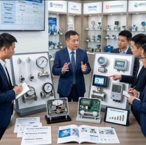
This guide gives distributors and agents a complete, field-grounded understanding of steam flow measurement with flow nozzles — from selection and installation through calibration, maintenance, troubleshooting, and digital integration. Every section is designed to help you recommend the right solution, close technically complex deals, and keep clients coming back.
🔍 Industry Insight: In thermal power generation alone, a 1% error in main-steam mass flow measurement on a 600 MW unit translates to an annual fuel cost miscalculation of approximately USD 800,000–1.2 million, depending on coal price. This is why steam flow measurement accuracy is not an engineering preference — it is a direct line to plant profitability and regulatory compliance.
1. Understanding Steam Flow Measurement Fundamentals
The Critical Role of Accurate Steam Flow Measurement

Steam is not just a fluid — it is a high-energy, phase-sensitive working medium. Its density, enthalpy, and mass flow rate change with every fluctuation in temperature and pressure. Measure it wrong, and the consequences cascade: overbilling or underbilling in steam distribution networks, efficiency penalties in turbine operations, off-spec product quality in chemical reactors, and failed compliance audits in regulated industries.
Accurate steam differential pressure flow measurement affects three critical business outcomes simultaneously. First, operational efficiency: a combined-cycle power plant that misreads main steam flow by 1.5% loses the ability to optimize combustion and turbine dispatch. Second, cost control: steam is an energy commodity, and metering accuracy directly determines fuel consumption benchmarking, energy purchasing decisions, and internal cost allocation. Third, regulatory compliance: environmental permits, ISO 50001 energy management certifications, and utility billing regulations all require traceable, calibrated flow data — with documented uncertainty budgets.
The consequences of measurement failure are not abstract. A coal-fired plant in Southeast Asia that operated with scale-fouled orifice plates on its main steam line for 14 months experienced a systematic 3.2% over-read in steam flow — which incorrectly showed the plant running at higher efficiency than it actually was. The operations team deferred a turbine maintenance action based on that false data. The result: an unplanned turbine outage costing USD 4.1 million in lost generation and repair costs.
Types of Steam Encountered in Industrial Settings
The type of steam present in a given pipeline profoundly determines which measurement approach delivers reliable accuracy. Getting this classification right before specifying any instrument is the most important single step in a steam flow measurement project.
| Steam Type | Typical Conditions | Density Behavior | Key Measurement Challenge |
|---|---|---|---|
| Saturated Steam | At saturation curve; P determines T (e.g., 10 bar → 180 °C) | Fully predictable from pressure alone | Maintaining dry condition; moisture ingress causes 8–12% over-reading |
| Superheated Steam | Above saturation curve; requires both P and T measurement (e.g., 250 bar, 560 °C) | Requires ASME Steam Tables; varies with both P and T | Temperature measurement accuracy critical; ±2 °C error → ±0.4% density error |
| Wet Steam | Below saturation curve; liquid droplets present (dryness fraction χ < 1.0) | Two-phase mixture; effective density requires dryness fraction (χ) | Nozzle throat erosion from droplet impingement; density errors up to 15%+ without χ correction |
Saturated steam is the most common steam type in industrial distribution networks — district heating, process heat exchangers, and hospital sterilization systems. Because its temperature and pressure are locked together by the saturation curve, a single pressure measurement is sufficient to determine steam density, which simplifies the flow calculation. However, it is thermodynamically unstable: any heat loss in the distribution pipe or any pressure drop across a valve causes partial condensation, generating wet steam — a two-phase mixture of steam and liquid water droplets.
Superheated steam dominates in power generation. It is steam heated beyond its saturation point, containing no liquid water. Main steam lines on a modern supercritical power unit typically operate at 250–280 bar and 560–600 °C. Because density varies with both temperature and pressure, mass flow calculation requires simultaneous pressure and temperature measurement — making the transmitter and compensation algorithm selection as critical as the primary element itself.
Wet steam is the most measurement-hostile condition. The liquid droplets in the flow accelerate nozzle throat erosion — particularly in orifice plates, whose sharp edges are especially vulnerable — and the dryness fraction (χ, defined as the mass fraction of vapor in the mixture) must be known to calculate true mass flow. Without a quality measurement, a wet steam reading carries a potential error of 8–15%, regardless of how accurately the differential pressure is measured.
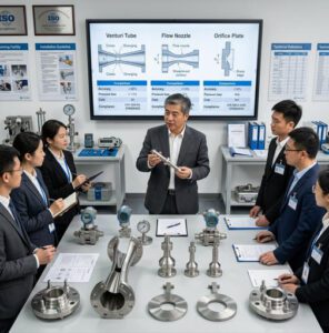
Why Flow Nozzles Outperform Alternative Technologies
Steam Application Performance Comparison — Key Criteria (Score out of 10)
Flow Nozzle — Overall Suitability for Steam
Orifice Plate — Overall Suitability for Steam
Vortex Meter — Overall Suitability for Steam
Venturi Tube — Overall Suitability for Steam
Turbine Meter — Overall Suitability for Steam
Composite score based on: accuracy, high-temp/pressure suitability, erosion resistance, maintenance interval, and pressure recovery. Scoring reflects high-temperature steam service above 300 °C.
Against orifice plates, the flow nozzle wins on every dimension that matters in steam service. The nozzle’s bell-mouth inlet eliminates the sharp edge that is progressively destroyed by steam erosion, condensate droplets, and thermal cycling. The solid machined body resists distortion under repeated pressure surges. Pressure loss is 25–35% lower, reducing long-run energy costs. And the discharge coefficient is more stable across the Reynolds number range, delivering better field accuracy even when installation conditions are imperfect.
Against Venturi tubes, the nozzle offers meaningful installation advantages. A Venturi tube’s diverging recovery section requires 5–8 pipe diameters of additional pipe length — a critical constraint in many existing plant piping arrangements. Flow nozzles are compact enough to fit where Venturis cannot, while still delivering better pressure recovery than orifice plates. For the cost-conscious distributor client, a flow nozzle is effectively the best achievable solution at intermediate cost.
Turbine meters و magnetic flow meters are simply not appropriate for high-temperature steam. Turbine meters rely on mechanical bearings that cannot survive repeated exposure to superheated steam at 400–600 °C. Magnetic flow meters require electrically conductive fluid — steam is not. The flow nozzle’s absence of moving parts, electronic components in the flow path, and sensitivity to electrical properties makes it uniquely suited to the steam environment. As our team at أدوات النمل اليشم routinely advises distributors: in steam above 350 °C, the realistic choice is between a flow nozzle and a Venturi — and space constraints usually decide in the nozzle’s favor.
2. Flow Nozzle Design Principles for Steam Applications
Core Design Considerations for High-Temperature Environments

Material Selection for Extreme Temperature Resistance
Material selection for a steam flow nozzle is not a catalog lookup — it is an engineering decision that determines whether the device maintains its calibrated geometry for two years or twenty. The wrong material choice in high-temperature steam service does not fail catastrophically; it drifts. The nozzle throat expands asymmetrically, the discharge coefficient shifts, and the measurement begins reading consistently 1–3% away from truth — an error that can go undetected for years without proactive calibration.
| Material | Max Temp | Max Pressure | Ideal Application | Standard |
|---|---|---|---|---|
| Carbon Steel | ~425 °C | Up to Class 1500 | Low-pressure saturated steam; utilities | ASTM A105 |
| SS 316 / 316L | ~650 °C | Up to Class 2500 | Standard superheated steam; chemical plants | ASTM A182 F316L |
| 1.25Cr-0.5Mo (P11) | ~540 °C | Up to Class 2500 | Power plant main steam, creep-resistant service | ASTM A182 F11 |
| 2.25Cr-1Mo (P22) | ~570 °C | Up to Class 4500 | Supercritical and ultra-supercritical steam | ASTM A182 F22 |
| Inconel 625 / 718 | ~800 °C | Up to Class 4500+ | Ultra-supercritical; corrosive steam with contaminants | ASTM B446 / B637 |
A critical design parameter often overlooked in nozzle specification is the thermal expansion coefficient of the throat material. A 316 SS nozzle with a design throat diameter of 80 mm at 20 °C expands to approximately 80.09 mm at 550 °C — a change that shifts the beta ratio and, consequently, the discharge coefficient. ISO 5167-3 accounts for this in its uncertainty calculation, but only if the correct thermal expansion data is applied in the flow computer’s sizing algorithm. Distributors should verify that the supplier’s documentation includes the temperature-corrected throat diameter at operating conditions — not just the cold bore dimension.
ISO 5167 Standards and Steam-Specific Requirements
ISO 5167-3:2022 is the governing international standard for flow nozzle geometry and installation. It specifies two primary nozzle profiles: the ISA 1932 nozzle و long-radius nozzle. For steam applications, the long-radius nozzle is generally preferred. Its discharge coefficient (Cd) uncertainty is ±0.8% across Reynolds numbers from 10⁵ to 10⁷ — significantly better than the ISA 1932’s ±1.5% at the lower end of that range. For high-velocity steam (Re typically 10⁶–10⁷), the long-radius profile delivers the best combination of accuracy and installation tolerance.
The standard requires beta ratios between 0.30 and 0.80 for long-radius nozzles. Throat surface finish must achieve Ra ≤ 10⁻⁴ × d (where d = throat diameter in mm) — for a 100 mm throat, that means Ra ≤ 10 μm. This is a machining standard that separates precision nozzle manufacturers from commodity suppliers. Ask any potential supplier for their dimensional inspection report format before placing an order: a compliant supplier will provide signed coordinate measuring machine (CMM) data, not just a visual inspection certificate.
For power plant steam turbine testing, ASME PTC 6 (Performance Test Code for Steam Turbines) sets even tighter requirements. ASME PTC 6 flow nozzles — the throat-tap nozzle variant — achieve measurement uncertainties as low as ±0.25% when properly calibrated and installed. This level of precision is what allows operators to detect whether a turbine’s actual heat rate matches its guaranteed performance within the contractual tolerance — a USD multi-million determination in large unit acceptance testing.
Pressure Drop Analysis and System Integration
Steam is expensive energy. Every Pascal of permanent pressure loss through a measurement device represents thermal energy that cannot be converted to work — it is simply wasted as turbulence and heat. The flow nozzle’s pressure recovery is significantly better than an orifice plate: a nozzle at beta = 0.6 recovers approximately 60–70% of the created differential pressure, while an orifice plate at the same beta recovers only 25–40%.
Orifice Plate — Pressure Distribution
Permanent Loss (60–70%)
High Energy Waste
Flow Nozzle — Pressure Distribution
Permanent Loss (30–40%)
Lower Energy Waste
Permanent pressure loss as % of created ΔP at beta = 0.6. Actual values depend on beta ratio and Reynolds number. Source: ISO 5167 engineering reference.
For a 200 mm main steam line flowing superheated steam at 100 bar, 450 °C, and 50,000 kg/h, the difference in permanent pressure loss between an orifice plate and a flow nozzle is approximately 8–12 kPa. Converting that to thermal energy waste over 8,000 operating hours per year: the orifice plate configuration wastes roughly 320–480 GJ/year more than the nozzle. At a steam generation cost of USD 12/GJ, that is USD 3,800–5,800 per year per measurement point in recoverable energy — energy that could otherwise produce useful work.
Temperature Compensation Mechanisms
Thermal expansion is not a side note for steam flow nozzles — it is a primary accuracy driver. A Cr-Mo alloy nozzle body (ASTM A182 F22) operating at 565 °C has a thermal expansion of approximately 14.6 mm/m relative to its cold dimension. For a 150 mm (D) nozzle throat in a 300 mm pipe, this translates to a beta ratio change of approximately 0.003 — which shifts the discharge coefficient by approximately 0.15%. This is within acceptable bounds for most process measurement applications, but must be accounted for in the sizing calculation and flow computer configuration.
Modern DP transmitters with multi-variable capability allow temperature compensation to be applied in real time. The flow computer receives the live process temperature signal, calculates the corrected throat diameter at operating temperature, applies the appropriate density correction from the embedded IAPWS-IF97 steam tables (the international standard steam property formulation), and outputs corrected mass flow. For distributors specifying complete measurement loops, recommending a multi-variable transmitter over a basic DP transmitter is a critical upsell with genuine technical justification — not a margin play.
3. Installation Best Practices for Maximum Performance
📺 The Differential Pressure Flow Measuring Principle — a technical walkthrough of how flow nozzles, orifice plates, and Venturi tubes create and measure differential pressure in industrial steam and gas systems.
Pre-Installation Assessment and Planning
The most common cause of flow nozzle underperformance is not a defective device — it is an inadequately planned installation. A technically excellent nozzle installed in the wrong location will consistently deliver mediocre results, and the poor performance will often be incorrectly attributed to the instrument rather than the piping arrangement.
Before any nozzle is ordered, conduct a piping system evaluation covering four key elements. First, map the upstream and downstream disturbances: record every elbow, tee, valve, reducer, and pump within 50 pipe diameters (50D) of the proposed measurement point. Any disturbance within this zone potentially affects the velocity profile at the nozzle throat. Second, obtain the actual pipe internal diameter at the measurement location — not the nominal size. Wall thinning from corrosion, heavy-wall schedule specifications, and weld bead protrusions all affect the effective pipe bore, which directly determines the beta ratio and thus the discharge coefficient calculation.
Third, confirm the pressure and temperature profile across the full expected operating range — minimum, normal, and maximum. Flow nozzles are sized for a specific design differential pressure at design conditions; operating significantly outside the design range degrades accuracy. Finally, assess accessibility for future maintenance: a flow nozzle installed between two fixed steel structures with no access platform is a maintenance liability that will eventually result in deferred calibration, measurement drift, and a frustrated client.
| Upstream Disturbance Type | Min. Upstream Run (β = 0.5) | Min. Upstream Run (β = 0.7) | Min. Downstream Run |
|---|---|---|---|
| Single elbow (one plane) | 14D | 20D | 6D |
| Two elbows (different planes) | 22D | 35D | 6D |
| Control valve (fully open) | 26D | 44D | 6D |
| Reducer (area ratio ≥ 0.5) | 10D | 18D | 6D |
| Fully open gate valve | 12D | 16D | 6D |
| Source: ISO 5167-3:2022, Table 1. Values shown for long-radius nozzle. Actual requirements vary with beta ratio; consult the full standard for intermediate beta values. D = internal pipe diameter. | |||
Proper Flow Nozzle Positioning and Orientation
Flow nozzles can be installed in horizontal, vertical upward, or vertical downward piping configurations — but each orientation has specific requirements that affect both accuracy and longevity.
Horizontal installation is the most common and least problematic. The nozzle axis must be level within ±1° to prevent gravity-induced flow profile asymmetry, and the pipe must be completely full of steam at all operating conditions. For saturated steam lines, ensure no cold spots exist upstream that could cause partial condensation and a liquid layer on the pipe bottom — a condition that creates severe measurement bias and accelerates nozzle erosion at the lower throat quadrant.
Vertical installation with upward steam flow is the second preferred orientation. It ensures any condensate drains away from the measurement point and prevents liquid accumulation in the nozzle throat. Vertical downward flow is acceptable but requires careful impulse line design, as condensate management in the low-pressure impulse line becomes more complex. In all vertical installations, the nozzle inlet cone must be precisely centered — off-center alignment by more than 0.5% of pipe diameter introduces measurable asymmetry in the discharge coefficient.
Differential Pressure Transmitter Integration
The DP transmitter is the second half of the measurement system — and a poorly matched or poorly installed transmitter negates even a perfectly machined nozzle. For steam applications, transmitter selection must consider three critical parameters: the differential pressure range, the static pressure rating, and the ability to handle steam impulse line conditions.
The design differential pressure is typically set at the maximum expected flow condition, with the transmitter ranged to 125% of that value to avoid overrange damage. However, because DP flow varies with the square of flow (ΔP ∝ Q²), a transmitter ranged for maximum flow produces only 25% of full-scale DP signal at 50% flow — and only 6.25% at 25% flow. For steam systems with significant flow turndown requirements, a transmitter with a high rangeability specification (50:1 or better) combined with square-root extraction in the flow computer is essential. Many of the smart pressure transmitters available today incorporate onboard diagnostics, self-zeroing, and HART/FOUNDATION Fieldbus communication that significantly improve the maintainability of the complete loop.
Differential Pressure Transmitter Impulse Line Design for Steam
Critical Impulse Line Design Requirements for Steam Service
- Slope: Minimum 1:12 downward slope from process tap to condensation pot — ensures reliable liquid leg formation
- Condensation pots: Required on both high-pressure and low-pressure impulse lines for saturated and superheated steam; liquid column balancing eliminates static head error
- DP transmitter position: Mount below the steam line and below the condensation pots — never above the taps in steam service
- Line length: Keep impulse lines as short as practical; maximum 10 m without heat tracing; trace longer runs to prevent freeze/condensate blockage
- Isolation valves: Install at the process tap connection for safe transmitter removal under pressure (block-and-bleed arrangement)
- Equalization valve: Five-valve manifold preferred for steam; allows zero verification without shutting down the line
- Material: Impulse lines must match process pipe material rating — SS 316 minimum for steam above 200 °C
Sealing and Gasket Selection for Steam Systems
Steam leaks at flange joints are not merely a safety and efficiency concern — they affect measurement accuracy. A leak on the high-pressure tap connection reduces the upstream pressure signal seen by the transmitter, artificially inflating the differential pressure reading and causing flow over-reading. A leak on the downstream side does the opposite. Either way, the measurement drift is systematic and progressive, making it particularly insidious because it looks like a slow calibration drift rather than an installation failure.
For steam above 260 °C, spiral-wound gaskets with a 316 SS winding and flexible graphite (or PTFE for lower temperature ranges) filler are the industry standard. These gaskets maintain sealing integrity through thermal cycling, whereas soft-seated gaskets (rubber, fiber) compress permanently under repeated thermal cycling and lose sealing force. Gaskets must be replaced at every nozzle removal — reusing a gasket on a high-temperature steam flange is a maintenance shortcut that invariably creates measurement problems within the next operating cycle.
4. Measurement Accuracy and Calibration Standards

Achieving and Maintaining High Measurement Accuracy
Accuracy in a steam flow nozzle system is a chain — and it is as strong as its weakest link. The total measurement uncertainty is not just the uncertainty of the nozzle’s discharge coefficient; it is the root-sum-square combination of every element in the measurement loop: the nozzle geometry, the pipe internal diameter measurement, the DP transmitter calibration, the temperature sensor accuracy, the pressure measurement accuracy, and the steam property data used in the density calculation.
| Uncertainty Source | Typical Contribution to Mass Flow Uncertainty | Mitigation |
|---|---|---|
| Nozzle discharge coefficient (Cd) | ±0.8% (long-radius, ISO 5167-3) | Lab calibration reduces to ±0.3% |
| Pipe internal diameter (D) | ±0.4–0.5% per 0.1% D error | Ultrasonic pipe gauge; multi-point measurement |
| DP transmitter calibration | ±0.1–0.3% FS (modern smart transmitter) | Annual in-situ zero check; 3-yearly calibration |
| Temperature measurement accuracy | ±0.4% per ±2 °C error (at 500 °C steam) | Calibrated RTD Class A; avoid thermowell vibration |
| Steam density data (IAPWS-IF97) | <0.1% (standard is highly accurate) | Confirm flow computer uses current IAPWS-IF97 |
| Installation effects (imperfect straight run) | 0–3% depending on deviation severity | Flow conditioning; meet ISO 5167-3 straight run |
| Combined Total Uncertainty (RSS) | ±1.0–1.8% (typical good installation) | ±0.5–0.8% achievable with lab-cal nozzle + full compensation |
In-Situ Calibration Techniques
True in-situ calibration of a flow nozzle — removing it from service and sending it to a primary calibration laboratory — is impractical in operating steam plants. The realistic calibration program for most installations is a combination of periodic verification (confirming the transmitter output is correct) with less frequent dimensional inspection (confirming the nozzle throat geometry is unchanged).
Transmitter verification can be performed without line shutdown using a five-valve manifold: close the high and low block valves, open the equalize valve, and confirm the transmitter reads zero differential pressure. Any non-zero reading indicates a calibration offset. Smart transmitters with built-in diagnostics can perform a partial self-verification automatically, logging zero drift trends over time. A drift exceeding ±0.1% of calibrated span per month warrants physical investigation of the impulse lines and transmitter.
Comparative measurement — installing a temporary clamp-on ultrasonic meter in parallel during a planned inspection window — provides a cross-check of the nozzle measurement without removing the nozzle from service. While clamp-on accuracy (±1–2%) is insufficient to calibrate the nozzle, it is sufficient to detect drifts greater than 2%, which is the threshold for immediate corrective action in most process applications.
Pressure and Temperature Compensation Strategies
Mass flow calculation for steam requires three inputs: differential pressure (ΔP), static line pressure (P), and steam temperature (T). The flow computer combines these using the ISO 5167 flow equation and the IAPWS-IF97 steam property formulation to calculate mass flow in kg/h or kg/s. Without pressure and temperature compensation, a steam flow nozzle system calculates only volumetric differential pressure — which can be 15–25% in error when actual steam conditions differ from the design-basis assumptions.
For superheated steam: both pressure and temperature inputs are mandatory. The density of superheated steam at 250 bar and 560 °C is approximately 94 kg/m³; at 240 bar and 540 °C (10 bar, 20 °C lower — a realistic operating variation), it drops to approximately 88 kg/m³ — a 6.4% change. Without live compensation, every operating condition that deviates from design by this margin introduces a direct 3.2% mass flow error (density enters the equation as a square root).
For saturated steam: pressure compensation alone is sufficient (temperature is uniquely determined by pressure on the saturation curve), which simplifies the measurement loop. However, ensure the flow computer’s steam property lookup is programmed for saturated conditions — some off-the-shelf transmitters default to superheated steam property tables, introducing systematic errors in saturated steam service.
Quality Assurance Protocols for Distributors and Agents
When you supply a flow nozzle measurement system to an end client, the documentation package you deliver is as important as the hardware. A complete QA package for a steam flow nozzle system should include: a dimensional inspection report with actual measured throat diameter, pipe internal diameter, and inlet profile coordinates (CMM data preferred); material test reports (MTR / EN 10204 3.1 minimum) for all pressure-retaining components; a performance calculation sheet showing the design Cd, beta ratio, design ΔP, and uncertainty budget at design conditions; and installation drawings with all required straight pipe dimensions explicitly marked.
This documentation package serves a dual purpose: it gives your client’s engineering team the data they need to commission the system correctly, and it gives you a defensible record in the event of a performance dispute. The distributors who routinely provide complete technical packages close more deals with major industrial clients — because the package demonstrates a level of technical competence that commodity distributors cannot match.
5. Long-Term Stability and Reliability in High-Temperature Environments
Factors Affecting Long-Term Performance Stability
A flow nozzle installed in high-temperature steam does not fail suddenly — it degrades slowly, and the degradation modes are well-understood if you know what to look for. The three primary degradation pathways are material erosion, scale and deposit buildup, and thermal fatigue.
Primary Degradation Mechanisms — Relative Impact on Measurement Accuracy Over Time
Impact severity on nozzle measurement accuracy. Field data from power generation and chemical processing applications. Actual impact depends on steam quality, velocity, and material selection.
Preventive Maintenance Programs for Extended Service Life
A well-structured preventive maintenance program for a steam flow nozzle system reduces the total lifecycle cost by extending replacement intervals and catching accuracy drift before it causes operational or financial impact. The program should be structured around three tiers of activity.
Tier 1 — Continuous/Routine (Monthly): Review the trend of the differential pressure output at standard operating conditions. A consistent upward drift in ΔP at constant flow conditions indicates nozzle fouling or partial impulse line blockage. A consistent downward drift suggests nozzle erosion (increasing effective throat area) or a high-pressure impulse line leak. Plotting this trend requires only a DCS historian and takes under 10 minutes per measurement point — but it catches 80% of problems before they become critical.
Tier 2 — Periodic (Annual Shutdown): Perform transmitter zero verification, inspect impulse lines for scale or blockage, drain condensation pots and verify they fill correctly, inspect all flange gaskets visually, and check nozzle position/alignment using a simple bore gauge. Replace gaskets regardless of apparent condition. This inspection takes 4–6 hours per measurement point and can typically be folded into a planned boiler/turbine maintenance outage without adding to outage duration.
Tier 3 — Major Inspection (Every 5–8 Years): Remove the nozzle for dimensional inspection against original CMM records. Measure throat diameter, inlet profile geometry, and surface finish. Compare against the original acceptance records and calculate whether the Cd shift is within acceptable limits. For a nozzle in clean, dry superheated steam service, dimensional changes at the 8-year mark are typically negligible — less than 0.05 mm on throat diameter, corresponding to less than 0.1% Cd shift. In wet or contaminated steam, the same interval may show 0.2–0.5 mm throat erosion, requiring replacement or recalibration.
Performance Degradation Indicators and Monitoring
⚠️ Early Warning Signs of Steam Nozzle Measurement Drift
- Differential pressure reading rising at constant known flow conditions — suggests fouling or blockage
- ΔP reading trending downward at constant flow — suggests erosion or high-side leak
- Increased scatter/noise in DP signal — impulse line partial blockage or valve seat wear
- Mass flow reads higher than boiler firing rate implies — check steam quality (wet steam causing density error)
- Transmitter zero drifts more than 0.05% FS/month between calibrations — check impulse line balance
- Steam leaks visible at instrument tap connections — immediate action required (gasket or fitting failure)
6. Industry-Specific Applications and Case Studies
Power Generation and Steam Turbine Applications

Power generation is the environment that defined flow nozzle technology and continues to drive its development. A modern 1,000 MW supercritical unit has 15–25 primary steam flow measurement points — main steam, hot reheat, cold reheat, boiler feedwater, and auxiliary steam lines — operating at conditions ranging from 40 bar/250 °C to 280 bar/600 °C. Every one of these measurement points is specified as a flow nozzle. No other primary element technology meets the simultaneous requirements of extreme pressure, extreme temperature, high velocity, and zero tolerance for moving parts.
Case Study — Power Generation
Improving Main Steam Measurement Accuracy in a 600 MW Coal-Fired Unit — Southeast Asia
Problem: A 600 MW coal-fired unit in Malaysia had been operating with orifice plates on its main steam and hot-reheat lines for 11 years. Quarterly performance tests consistently showed the unit running at 96.4% of design heat rate — but the operations team suspected the measurement system, not actual thermal performance, was driving the anomaly.
Finding: Dimensional inspection during a planned overhaul found that the main steam orifice plates had experienced edge erosion (average edge radius: 0.8 mm vs. 0.2 mm design maximum) due to periodic wet-steam ingress. The discharge coefficient had shifted by approximately +2.1% — meaning the plant had been over-reading main steam flow by 2.1% for an estimated 4–6 years.
Solution: Replaced all four main steam and hot-reheat measurement points with ISO 5167-3 long-radius flow nozzles in ASTM A182 F22 (2.25Cr-1Mo), with full dimensional certification. Added temperature compensation (multi-variable DP transmitters with RTD input) for superheated steam mass flow.
Result: Post-modification ASME PTC 6 performance test confirmed actual heat rate at 97.8% of design — a meaningful improvement in measured efficiency that unlocked capacity payment eligibility. The corrected steam flow data also revealed an actual steam turbine degradation of approximately 0.7% from design, which was scheduled for corrective maintenance. Total annual financial impact of accurate data: estimated USD 2.3 million in combined capacity payment recovery and avoided fuel over-procurement.
Chemical Processing and Thermal Operations
Chemical plants use steam as a reactant, a heat transfer medium, a stripping agent, and a driving force for ejectors and turbine-driven pumps. Accurate steam flow measurement in this environment affects both product quality and raw material accounting. A pharmaceutical reactor that receives 5% more steam than the recipe specifies may overheat the product batch, causing out-of-spec yields and batch rejection costs that dwarf the cost of the flow measurement system that failed to control it.
Case Study — Chemical Processing
Enhancing Product Consistency Through Precise Steam Measurement — Specialty Chemical Plant, Germany
Problem: A specialty chemical plant producing polymer intermediates was experiencing batch-to-batch viscosity variation that exceeded quality specification ±8% of the time. The reactor used steam as a heat source during a critical polymerization step. After eliminating other variables, the investigation focused on steam flow measurement accuracy.
Finding: The installed orifice plate had a worn edge (estimated Cd shift +1.4%) and no temperature compensation — the flow computer used a fixed steam density based on design conditions, not live measurements. Actual steam conditions varied from 8 bar/172 °C (saturated) to 9 bar/180 °C, introducing a density variation of approximately 8% that was completely uncompensated. Total flow measurement error range: ±4–6%.
Solution & Result: Installation of an ISO 5167-3 long-radius nozzle with integrated pressure compensation. After commissioning, batch viscosity variation fell to ±1.8% — within specification on 99.2% of batches vs. 92% previously. Estimated annual savings from reduced batch rejection and rework: EUR 280,000. The measurement system upgrade cost: EUR 18,500.
Food and Beverage Industry Applications
Steam in food and beverage processing is a critical process utility — and in many applications, a direct contact with product. Sterilization-in-place (SIP) and pasteurization systems must deliver precise steam flow at validated temperature and time combinations to achieve regulatory-required sterility assurance levels (SAL ≤ 10⁻⁶). FDA guidance on aseptic processing requires documented, validated steam delivery parameters — making measurement traceability a regulatory requirement, not a quality aspiration.
Case Study — Food & Beverage
Reducing Product Waste Through Accurate Steam Flow Data — Dairy Processing Facility, New Zealand
Problem: A large dairy processor was experiencing UHT milk production losses of approximately 3.2% — above-target product waste during pasteurization that the operations team attributed to steam flow over-supply. The installed vortex meters on the pasteurization steam lines had reached the end of their calibration interval and were showing ±2% accuracy.
Solution: Replaced vortex meters with flow nozzles (SS 316L, ISO 5167-3) with integrated DP transmitters and live steam pressure compensation. Calibrated against traceable primary standards; full dimensional reports included in the FDA validation documentation package.
Result: Product loss reduced from 3.2% to 1.1%. Annual saving at plant production volumes: NZD 420,000. FDA compliance documentation for the new system was completed in 3 weeks with zero audit findings — the full dimensional and calibration package from the nozzle supplier made the validation straightforward.
HVAC and Facilities Management Systems
Case Study — HVAC / District Heating
Optimizing Energy Consumption in a Multi-Building District Heating Network — Scandinavia
Problem: A Scandinavian university campus with 18 interconnected buildings ran a central steam distribution network for heating and hot water. Energy allocation between buildings — and billing to individual department cost centers — was based on flow nozzle measurements that had not been inspected for 9 years. An energy audit revealed that the total metered steam consumption across all building meters was 7.4% higher than the central generation meter reading — a clear indication of systematic measurement error across the distribution network.
Root Cause: Five of the 18 building flow nozzles showed scale deposits in the throat reducing effective bore area, artificially increasing the indicated flow. Three others had damaged seals causing partial impulse line leaks, biasing DP readings.
Result: Full nozzle inspection, cleaning, and seal replacement program. Post-maintenance reconciliation showed network imbalance reduced to 0.9% — within acceptable meter uncertainty. Annual energy cost reallocation between building users: EUR 140,000. One building that had been over-billed for 4+ years received a EUR 65,000 credit adjustment.
7. Selecting and Specifying Flow Nozzles for Your Customers
Technical Specification Development Process
The most effective way to serve an industrial client is to arrive at the first conversation with a structured data request — and the ability to turn that data into a defensible specification. The following checklist covers the minimum application data required to size and specify a steam flow nozzle correctly. Distributors who use this checklist systematically eliminate the most common cause of specification errors: incomplete application data.
📋 Steam Flow Nozzle Specification Checklist — Minimum Application Data
Process Conditions
- Steam type: saturated / superheated / wet
- Operating pressure (min / normal / max)
- Operating temperature (min / normal / max)
- Mass flow rate (min / normal / max)
- Steam quality / dryness fraction (if wet steam)
- Presence of condensate, carryover, or contaminants
Piping Configuration
- Pipe internal diameter (measured, not nominal)
- Pipe schedule and material
- Available upstream straight run (in D)
- Available downstream straight run (in D)
- Nearest upstream disturbance type and distance
- Pipe orientation (horizontal / vertical)
Regulatory and Documentation
- Applicable standard (ISO 5167 / ASME PTC 6 / other)
- Required measurement uncertainty
- Required material certifications (3.1 / 3.2 / PMI)
- Hazardous area classification (ATEX / IECEx)
- Flange standard (ANSI / DIN / JIS) and rating
- Required output signal (4–20 mA / HART / Fieldbus)
Vendor Evaluation and Selection Criteria
Not all flow nozzle suppliers are equal, and the difference matters significantly in steam applications. A nozzle with a throat diameter 0.3 mm out of tolerance from a substandard machining operation will deliver a systematic bias of approximately 0.9% in mass flow — a hidden error that will never be caught without dimensional inspection records.
Evaluate potential suppliers across five dimensions. Manufacturing capability: can they produce the required throat surface finish (Ra ≤ 10⁻⁴ × d) and provide CMM dimensional records? Material traceability: can they provide EN 10204 3.1 material test reports with chemical composition and mechanical properties traceable to the original mill certificate? Standards expertise: do their engineers understand the specific requirements of ISO 5167-3 and ASME PTC 6, or are they sizing by generic catalog tables? After-sales support: will they provide technical assistance to your installation team during commissioning, not just ship the hardware? And delivery reliability: a nozzle that arrives two weeks late when the plant shutdown is already in progress is worse than no nozzle at all.
At أدوات النمل اليشم, our throttling device program — including flow nozzles, orifice plates, and Venturi tubes — is built around ISO 5167 compliance with full dimensional inspection documentation and EN 10204 3.1 material certification as standard. For distributors building a technical product portfolio for industrial steam applications, having a manufacturer that can supply the complete documentation package is not a luxury — it is the baseline for competing in the engineering-driven segment.
Customization Options for Specialized Applications
Most steam flow nozzle applications can be handled with standard ISO 5167-3 long-radius geometry in a standard alloy. But a meaningful portion of high-value applications require customization — and that customization is where distributors with strong technical partnerships capture the highest margins and deepest client relationships.
Common customization requirements include non-standard pipe sizes (DN 750, DN 900 are increasingly common in large combined-cycle plants), weld-in nozzle designs for ultra-high-pressure service where flanged connections create unacceptable leak risk, special bore coatings (chrome carbide, tungsten carbide) for wet-steam erosion resistance in difficult services, and dual-chamber designs for bidirectional flow measurement in steam balance applications. Each of these custom requirements is best resolved early in the project — a nozzle designed from the outset for a specific unusual requirement is far more reliable than one adapted from a standard design after the fact.
8. Troubleshooting Common Issues and Performance Problems
Measurement Accuracy Issues and Resolution
| Symptom | Most Likely Cause | Diagnostic Step | Corrective Action |
|---|---|---|---|
| Flow reads high; stable but biased upward | Throat erosion (Cd increase); wet steam density error | Check steam quality; perform nozzle dimensional inspection | Replace nozzle if throat worn; add steam trap upstream for quality improvement |
| Flow reads low; stable but biased downward | Throat fouling (scale deposit); high-pressure impulse line leak | Inspect HP impulse line for leaks; schedule nozzle cleaning | Clean impulse lines; clean nozzle throat during next outage |
| Noisy/unstable DP signal | Partial impulse line blockage; two-phase flow at nozzle; vibration | Purge impulse lines; check for condensate in steam; inspect pipe supports | Increase transmitter damping as interim; resolve root cause |
| Zero reads non-zero (transmitter equalized) | Unequal condensate legs; transmitter zero drift; impulse line imbalance | Drain and re-fill condensation pots equally; re-zero transmitter | Verify condensation pot fill procedure; recalibrate transmitter |
| Sudden step change in reading | Complete impulse line blockage; gasket failure; transmitter failure | Check transmitter health diagnostics; inspect for steam leaks at flange | Replace gaskets; clear blockage; replace transmitter if failed |
Installation-Related Problems
The most common installation-related accuracy problem is insufficient upstream straight pipe — and it is also the most commonly denied. Plant engineers who invested significant effort in a piping design are reluctant to acknowledge that the 10D upstream run they specified is producing 3% flow bias. The practical diagnostic is straightforward: if the measurement system is producing readings that are consistently inconsistent with mass balance or heat balance expectations, and the transmitter calibration checks out, the first action is to review the actual (as-built) upstream piping arrangement against ISO 5167-3 requirements. In brownfield retrofits, this is almost always where the problem lies.
Transmitter range mismatch is the second most common installation problem. A steam flow nozzle system designed for a maximum flow that the plant rarely achieves will spend most of its time reading in the lower 10–15% of the DP range — where transmitter accuracy is expressed as a percentage of full scale, making the absolute flow error disproportionately large. The solution is either to resize the nozzle (change the beta ratio to generate a larger ΔP at normal flow) or to replace the transmitter with a model that has a higher rangeability specification. See the flow meter selection guide for a structured approach to sizing verification.
Maintenance and Repair Procedures
The most valuable maintenance practice for a steam flow nozzle system is also the simplest: keeping detailed records. Document every transmitter zero check, every impulse line purge, every gasket replacement, and every visual inspection with date, technician name, and findings. When a measurement problem eventually appears — and in a high-temperature steam environment, it will — this historical record is the roadmap that allows the root cause to be identified in hours rather than days.
For gasket and seal replacement, the procedure sequence matters as much as the component selected. On a steam line, always depressurize and cool the system before flange disassembly — this is non-negotiable from a safety standpoint. After reassembly with new spiral-wound gaskets, perform a hydraulic test or slow pressurization with steam at 10% of operating pressure before reaching full operating conditions, confirming seal integrity at each step. For post-maintenance measurement verification, allow the system to reach full operating temperature (which may take 2–4 hours for heavily insulated main steam lines) before taking calibration reference readings.
9. Regulatory Compliance and Industry Standards
International Standards and Certification Requirements

| Standard / Directive | Scope | Key Requirement | Region |
|---|---|---|---|
| ISO 5167-3:2022 | Flow nozzle geometry, installation, uncertainty | Dimensional compliance; straight pipe; Cd tables | Global |
| ASME MFC-3M | DP flow measurement in closed conduits | North American equivalent to ISO 5167 | North America |
| ASME PTC 6 | Steam turbine performance testing | Throat-tap nozzle; uncertainty ≤ ±0.25% | Global |
| ASME B16.5 | Pipe flanges and flanged fittings | Flange rating (Class 150–4500) for steam pressure rating | Global |
| PED 2014/68/EU | Pressure Equipment Directive | CE marking; conformity assessment; pressure vessel design | EU/EEA |
| ISO 50001 | Energy Management Systems | Traceable energy metering; measurement uncertainty budgets | Global |
| ATEX 2014/34/EU / IECEx | Hazardous area equipment | Ex-rated transmitters for Zone 1/2 steam environments | EU / Global |
Customer Audit and Compliance Support
Industrial clients in regulated industries face increasing pressure to document the performance of their measurement systems. ISO 50001 energy management certification requires traceable measurement data with documented uncertainty budgets. Environmental permit compliance requires verifiable steam consumption and emissions data. In the pharmaceutical sector, FDA validation protocols require documented evidence that every measurement in a product-contact process meets specified performance criteria.
Distributors who understand these compliance frameworks can provide genuine value beyond the hardware: helping clients assemble the correct documentation package, training installation teams on the specific requirements of ISO 5167-3 dimensional compliance, and providing an independent technical resource during regulatory agency inspections. This advisory role is where the most durable client relationships are built — and where the distinction between a distributor and a valued technical partner becomes concrete.
10. Digital Integration and Smart Monitoring Systems
IoT and Advanced Monitoring Capabilities
The flow nozzle itself is a passive mechanical element — its value is entirely determined by the quality of the measurement loop surrounding it. In the Industry 4.0 era, that loop increasingly extends from the process taps through smart transmitters, industrial networks, cloud-based analytics platforms, and AI-driven predictive maintenance engines.
Modern smart DP transmitters with HART 7 or FOUNDATION Fieldbus communication push far more than a 4–20 mA flow signal. They transmit real-time diagnostic data: process temperature at the transmitter electronics (useful for detecting thermal overload in poorly insulated impulse lines), static pressure on both high and low sides (revealing partial valve closures or blockages), and internal electronics health flags. For a steam flow measurement loop, a transmitter that sends this diagnostic data to the plant DCS historian allows the operations team to track measurement system health continuously — not just at annual calibration intervals.
🌐 Real-Time Data Collection
Smart transmitters log ΔP, static pressure, temperature, and diagnostics at configurable intervals (1–60 seconds). Cloud-connected gateways aggregate data from multiple measurement points into a unified dashboard accessible from any device.
🤖 Predictive Maintenance AI
Machine learning algorithms trained on historical ΔP trend data detect anomalies — gradual fouling, progressive erosion, impulse line degradation — up to 30–60 days before they cause measurable accuracy loss. This converts maintenance from reactive to predictive, eliminating unplanned outages.
📊 Energy Analytics
Steam mass flow data integrated with fuel consumption and power output data enables real-time specific steam consumption (kg/kWh) tracking. Deviations from benchmark trigger automated alerts — catching turbine degradation, heat exchanger fouling, and steam losses within hours rather than months.
🔌 Industrial Protocol Integration
HART, PROFIBUS PA, FOUNDATION Fieldbus, and Modbus TCP/IP are all available on current-generation DP transmitters. ERP integration via OPC-UA allows steam consumption data to flow directly into SAP or other enterprise systems for automated energy accounting and purchasing optimization.
Future-Proofing Your Measurement Systems
Distributors who help clients think about the 10-year lifecycle of their measurement infrastructure — rather than just the next purchase — build advisory relationships that generate repeat business. Three forward-looking considerations are particularly relevant for steam flow measurement systems being specified today.
First, scalability of digital infrastructure: a plant that installs HART-enabled transmitters today can add IIoT gateway devices in the future without replacing any hardware. Specifying HART 7-capable transmitters costs no more than basic 4–20 mA devices, but provides the digital pathway for future remote monitoring upgrades.
Second, carbon accounting requirements: steam generation is a major source of industrial CO₂ emissions. As carbon pricing mechanisms expand globally (EU ETS, China ETS, emerging national schemes), accurate steam flow measurement directly affects a client’s carbon liability calculation. A measurement system that delivers ±0.5% uncertainty vs. ±3% uncertainty represents a meaningful difference in carbon credit accounting — and a financial risk for clients whose measurement systems are not audit-ready.
Third, compatibility with digital twin platforms: major industrial operators are deploying digital twin models of their process plants for simulation, optimization, and operator training. These platforms depend on high-quality real-time process data — including steam flow — to function accurately. A plant with calibrated, diagnostically healthy differential pressure measurement systems providing reliable steam flow data is far better positioned to benefit from digital twin technology than one with aging, poorly maintained measurement infrastructure.
Positioning Flow Nozzles as the Optimal Solution
Why Flow Nozzles Remain the Industry Standard
Flow nozzles have been the primary element of choice for steam flow measurement in demanding industrial applications for over 80 years. That longevity is not inertia — it is the result of consistently outperforming every available alternative on the combination of criteria that matter most in steam service: durability in extreme temperature and pressure environments, measurable accuracy advantage over orifice plates in field conditions, lower long-term energy penalty than orifice plates, wider installation compatibility than Venturi tubes, and zero moving parts to fail in the harsh steam environment.
Strategic Advantages for Distributors and Agents
The strategic case for building a flow nozzle capability in your distribution portfolio goes beyond individual project margins. Steam flow measurement is a recurring need in every thermal power plant, chemical processor, food and beverage manufacturer, and district heating operator — applications that buy instrumentation every 5–15 years per point, with 20–50 measurement points per facility. A client relationship built on demonstrated technical expertise in steam flow measurement is a relationship that generates multiple equipment cycles and associated service revenue over decades.
The distributors who win these relationships consistently are not the ones with the lowest catalog price. They are the ones whose applications engineers can walk into a client’s plant engineering meeting, review the P&ID, identify the measurement points where accuracy is costing the client money, quantify that cost in the client’s financial terms, and propose a specification-compliant solution with complete documentation. That capability — technical credibility in the client’s engineering language — is what this guide is designed to help you build.
Implementation Roadmap for Your Organization
Building technical expertise in steam flow measurement within your sales team starts with three practical actions. First, develop a standard application data request form based on the specification checklist in Section 7 — use it on every steam measurement inquiry, without exception. This disciplines your team to gather the right data and signals technical seriousness to clients. Second, build a TCO comparison tool that translates pressure drop differences and maintenance interval differences into dollar values for your specific market’s energy costs and labor rates. This converts a technical comparison into a business case. Third, develop relationships with two or three reference client sites — plants where your flow nozzle installations have documented performance — and ask permission to use their data in proposals. A real performance number from a real plant in the same industry is more persuasive than any specification sheet.
Ready to Become the Go-To Expert in Steam Flow Measurement?
Download our comprehensive Steam Flow Measurement Technical Resource Package — including sizing calculators, specification templates, installation checklists, and troubleshooting guides designed specifically for B2B distributors and agents.
Or schedule a 30-minute consultation with our steam measurement specialist to discuss how to optimize your product offerings and increase customer satisfaction.
Jade Ant Instruments — ISO-certified flow measurement manufacturer. Throttling devices, flow nozzles, and complete DP measurement systems for industrial steam applications.
📖 Key Terms Glossary
Dryness Fraction (χ)
The mass fraction of vapor in a wet steam mixture. χ = 1.0 means 100% dry steam; χ = 0.90 means 10% liquid by mass. Required for accurate wet steam density and mass flow calculation.
IAPWS-IF97
The International Association for the Properties of Water and Steam — Industrial Formulation 1997. The international standard for steam property data (density, enthalpy, entropy) used in flow computers for mass flow calculation.
Discharge Coefficient (Cd)
A dimensionless correction factor that accounts for the difference between ideal and actual flow through a nozzle. Defined by ISO 5167-3 for each nozzle geometry; for a long-radius nozzle, Cd ≈ 0.98–0.995 at high Reynolds numbers.
Beta Ratio (β)
Throat diameter divided by pipe internal diameter. Determines sensitivity (higher β = lower ΔP per unit flow) and pressure loss characteristics. Standard range for flow nozzles: 0.30–0.80.
Condensation Pot
A small vessel installed in the impulse line of a steam DP measurement system. Steam condenses in the pot, creating a stable liquid column (wet leg) that protects the DP transmitter from direct steam contact and ensures equal hydrostatic head on both impulse lines.
ASME PTC 6
ASME Performance Test Code 6 for Steam Turbines. The international standard for steam turbine acceptance testing, specifying flow nozzle requirements that achieve measurement uncertainties as low as ±0.25% for turbine performance verification.
Permanent Pressure Loss
The portion of the differential pressure created by the flow element that is not recovered after the measurement point — representing energy permanently dissipated as heat. For a flow nozzle at β = 0.6, approximately 30–40% of the created ΔP is permanent loss.
EN 10204 3.1 / 3.2
European standard for material test reports. 3.1 = manufacturer’s own inspection report; 3.2 = independently witnessed by third-party inspector. Critical for pressure-retaining components in steam systems above certain pressure and temperature thresholds.
الأسئلة المتداولة
📚 Technical References and Further Reading
- ISO 5167-3:2022 — Measurement of Fluid Flow: Nozzles and Venturi Nozzles
- ASME Performance Test Codes — Including PTC 6 Steam Turbines
- Engineering ToolBox — Orifice, Nozzle, and Venturi Flow Meter Principles
- Jade Ant Instruments — Complete Vortex Flow Meter Guide for Steam and Gas
- Jade Ant Instruments — Flow Meter Selection Guide: 5 Factors Engineers Use
- Jade Ant Instruments — Smart Pressure Transmitter Comparison for Industrial Applications
- ISA InTech — Using Flow Meters to Improve Boiler Efficiency
- Triad Measurement — ASME PTC 6 Flow Sections Explained