Advanced Tips for Getting More from Your Gas Flow Meter: A Technical Guide for Industry Professionals

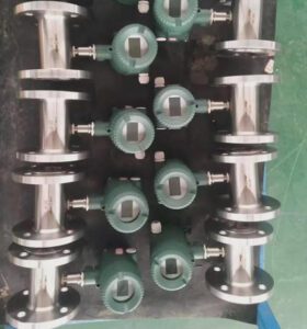
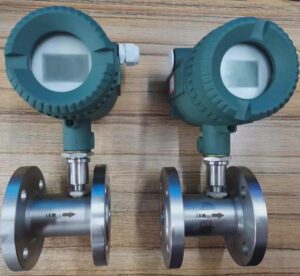
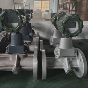
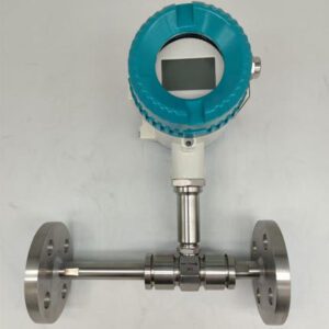
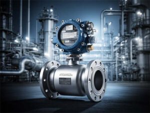
A vortex meter mounted in line. How it is installed matters about as much as which model you buy.
1. Executive Summary
A gas flow meter rarely fails all at once. It drifts a little each month or collects a thin coating, or electrical noise creeps into its signal until the numbers stop matching reality. Often nobody notices until a billing dispute, a failed audit, or a process upset forces the question.
This guide is for the people who have to live with those numbers: OEM and skid builders, EPC contractors and system integrators, instrument distributors, MRO teams, and municipal and utility operators. It skips the textbook material and covers the field problems that eat into accuracy and uptime. These include calibration decay, drift, fouling, signal noise, poor installation, and the hidden costs of buying the cheapest meter.
At Jade Ant Instruments, most of our service calls about “bad meters” turn out to be about something else: a missing filter, a second ground connection, or a meter installed six diameters from a control valve. The tips below come from fixing problems like those.
Quick definition: Gas flow meter. An instrument that measures how much gas moves through a pipe over time, either as volume (m³/h) or as mass (kg/h). Common types for gas are thermal mass, vortex, turbine, ultrasonic, and differential pressure.
What you will get from this guide:
- Calibration methods that hold up in real field conditions, not only on a test bench
- Verification routines that keep auditors and billing partners satisfied
- A step-by-step way to find the cause of drift before you replace hardware
- Design choices that stop fouling and corrosion from the start
- Wiring, installation, and diagnostics practices that extend meter life
- A total cost of ownership view for OEMs and EPCs, plus a checklist for digital readiness
2. Precision Calibration: Beyond the Basics
Accurate calibration is the foundation of reliable measurement, but standard procedures often fall short in dynamic field environments.
A meter calibrated at a single point in a clean lab can be accurate at 50% flow and still miss by 3% at 10% flow. Many field processes spend a lot of their time near the low end of the range: night loads, idling compressors, digesters in winter.
Quick definition: Turndown ratio. The highest flow a meter can measure accurately divided by the lowest. A 100:1 thermal meter rated for 1,000 Nm³/h stays within spec down to 10 Nm³/h.
Use multi-point calibration across the full turndown range
Calibrate at five points or more: roughly 10%, 25%, 50%, 75%, and 100% of maximum flow. Each point should use NIST-traceable reference standards. “Traceable” means an unbroken, documented chain of comparisons links your calibration back to a national standard. For high-pressure natural gas, the NIST natural gas flow calibration service page shows how primary standards connect to the labs that calibrate custody meters.
Industry insight: Distributors can win business by asking for the “as-found / as-left” data at every calibration point, not just a pass/fail stamp. As-found shows how the meter drifted in service. As-left shows how it was corrected. Over two or three cycles, those numbers tell you the right recalibration interval for that particular site.
Verify in place when the meter can’t come out
Some skid-mounted meters are welded in or boxed in, and some can’t be removed without stopping a process that has no bypass. Pulling them for calibration costs money. Portable prover systems and clamp-on ultrasonic reference meters let you check accuracy on site instead.
A practical routine for skid builders and MRO teams:
- Mount a clamp-on reference meter on a straight section near the installed meter.
- Log both readings together at low, mid, and high flow for about 15 minutes at each point.
- If the difference is larger than the combined uncertainty of the two meters, schedule a full lab calibration.
- If it is within tolerance, record the result and extend the interval.
Base recalibration on process severity, not the calendar
A fixed 12-month interval is simple to manage, but it wastes money on clean dry-air meters and leaves meters in dirty service exposed for too long.
| Service Condition | Example Applications | Suggested Verification | Suggested Full Calibration |
|---|---|---|---|
| Clean, dry, stable | Instrument air, nitrogen, dry natural gas | Every 12 months | Every 24–36 months |
| Moderate contamination | Compressed air after filter, boiler fuel gas | Every 6 months | Every 12–24 months |
| High particulate or moisture | Compressor discharge, unfiltered plant air | Every 3 months | Every 12 months |
| Corrosive or variable composition | Biogas, landfill gas, flare gas | Every 3 months | Every 6–12 months |
| Custody transfer / billing | Utility gate stations, fuel sales | Per contract or regulator | Annually at minimum |
3. Field Verification Protocols for Continuous Confidence
Proactive verification prevents undetected errors that compromise billing, safety, and process control.
Verification is not the same as calibration. Calibration adjusts the meter. Verification only confirms that the meter is still behaving as expected, and it can often be done without breaking a flange.

Ultrasonic gas meters log signal and sound-speed diagnostics that make remote verification practical.
Run built-in simulation and zero checks during planned outages
Most smart transmitters have a simulation mode that sends a known signal through the electronics, and a zero check done at confirmed no-flow. Put both into your shutdown checklist. They take minutes, and they separate “the sensor is wrong” from “the electronics or wiring is wrong.”
Quick definition: Zero check. Confirming that the meter reads zero when the gas is truly not moving. A meter that shows 0.8% of span with the line isolated has a zero offset, and that offset is added to every reading.
Keep time-stamped verification logs for compliance
Auditors working to API, AGA, or ISO frameworks want evidence as well as results. A good log records the meter tag, serial number, date and time, technician, method, reference equipment ID, as-found value, and pass/fail. EPC contractors should write this log format into the turnover package so the owner doesn’t have to invent one after start-up.
Use remote diagnostics across distributed networks
A utility with 300 district metering points can’t send a technician to each one every quarter. IIoT platforms can collect health data from every meter over cellular or LoRaWAN links. IIoT (Industrial Internet of Things) means field devices that report data over a network. Typical data includes signal quality, sensor temperature, and alarm counts. Crews then go only to the sites that are trending the wrong way.
Industry insight: Several water and gas utilities have moved from time-based rounds to exception-based rounds with this approach. Their technicians stop spending most of the day confirming that healthy meters are healthy.
4. Diagnosing and Correcting Measurement Drift
Unexplained drift leads to financial losses and compliance risks. Understand the root cause before replacing hardware.
Quick definition: Drift. A slow, steady change in a meter’s output while the true flow stays the same. Drift usually pushes readings in one direction. Readings that jump around in both directions usually point to noise or flow disturbance instead.
Illustrative drift pattern for a thermal sensor in compressed-air service. An oil-mist film builds up on the sensor, and the error grows each month unless the gas is filtered.
Step 1: Isolate environmental factors
Before blaming the meter, check its surroundings:
- Temperature gradients. An outdoor meter in direct afternoon sun can see its electronics housing heat up by 20 °C or more, which can shift some sensor outputs.
- Vibration. Meters near reciprocating compressors or pumps pick up mechanical energy. Vortex meters are the most sensitive, because vibration looks like vortex signals to them.
- Pressure transients. Fast-closing valves and compressor load/unload cycles send pressure spikes through the line and disturb readings.
Step 2: Correlate drift with process history
Pull 6 to 12 months of trend data and put it next to your process events. Did the site change fuel supplier? Start blending hydrogen? Add a new branch line upstream? A meter calibrated for pure methane will read wrong on a gas blend with more ethane or CO₂, because thermal and acoustic properties shift with the mix. In that case the meter is working correctly. Its gas-property settings no longer match the gas.
Step 3: Check alignment and mounting
A gasket sticking even 2–3 mm into the bore, or a flange offset of a few millimeters, can disturb the flow profile enough to shift readings. On insertion probes, check depth and rotation. A probe turned 10° off the flow axis is a common source of error nobody explains.
Drift diagnosis quick reference
| Symptom Pattern | Most Likely Cause | First Action |
|---|---|---|
| Slow, one-direction offset over months | Sensor fouling or coating | Inspect and clean sensor |
| Offset that appears after a process change | Gas composition or reference condition mismatch | Review gas settings and Nm³ vs Sm³ base |
| Error worse in winter | Temperature compensation fault | Compare meter temperature with reference thermometer |
| Error only at low flow | Below minimum velocity or Reynolds number | Check sizing; consider reduced-bore meter |
| Readings with no flow | Vibration or electrical noise | Check pipe supports and grounding |
For a longer diagnostic workflow built for channel partners, our field troubleshooting checklist for gas meters goes through each failure category step by step.
5. Combatting Fouling, Corrosion, and Contamination
Harsh industrial environments degrade performance. Design mitigation into your system from day one.
Contamination is cheaper to prevent than to fix. A coalescing filter costs less than one unplanned site visit.
Choose wetted materials for the gas you actually have
“Wetted” parts are the parts that touch the process gas. For most dry industrial gases, 316L stainless steel is enough. Biogas and landfill gas are harder on equipment. They carry hydrogen sulfide (H₂S), moisture, CO₂, and siloxanes. Siloxanes are silicon compounds from consumer-product waste, and they leave hard, glassy deposits when heated.
| Gas Service | Main Threat | Recommended Wetted Material |
|---|---|---|
| Instrument / compressed air | Oil mist, water | 316L stainless steel |
| Dry natural gas | Pipeline debris | 316L stainless steel |
| Biogas, low H₂S (<500 ppm) | Moist CO₂, mild corrosion | 316L with upstream moisture removal |
| Landfill gas, high H₂S | Sulfide corrosion, siloxanes | Hastelloy C-276 or ceramic-coated sensors |
| Chlorine or acid gases | Severe chemical attack | Hastelloy, PTFE-lined, or specialty alloys |
We cover the biogas side in more detail in our guide to thermal mass metering in biogas and digester service. It includes material selection and moisture handling for digesters.
Filter upstream of thermal and ultrasonic meters
Thermal mass meters work on the thermal dispersion principle: a heated sensor loses heat to the passing gas. Any film on that sensor, such as oil, dust, or moisture, acts like insulation, and the meter reads low. Ultrasonic transducers lose signal strength when deposits build up on their faces.
The fix is simple: a particulate filter plus a coalescing filter upstream. A coalescing filter merges fine droplets into larger ones that drain away.
Use self-cleaning or purge designs in dirty service
For custody-transfer points in dirty environments, choose vortex meters with self-cleaning bluff body designs, or add a purge connection that blows clean gas across the sensor on a schedule. A multivariable vortex flow meter with built-in temperature and pressure compensation also means fewer sensors and fewer places for dirt to collect.
Industry insight: One expense keeps showing up in MRO budgets: teams replacing thermal probes every year in compressor-discharge service. In most of these cases the problem is a missing filter. The probe is not defective.
6. Signal Integrity and Noise Reduction Strategies
Poor signal quality undermines even the most accurate meter design.
A meter can measure perfectly, and the control room can still see garbage. The 4–20 mA loop between the two is where many problems start.
Quick definition: Ground loop. When a signal circuit is grounded at two points with slightly different electrical potential, current flows through the signal wire itself. The result is a steady offset or a 50/60 Hz ripple on the reading.
Shield cables and ground at one point only
Use twisted-pair shielded cable. Ground the shield at one end only, usually at the control-panel end. Keep signal cables at least 300 mm away from VFD (variable frequency drive) power cables, and cross them at 90° where they must meet. Plants full of VFDs, welders, and large motors need this discipline most.
Protect and condition signals for legacy DCS/PLC systems
In hazardous areas, intrinsically safe (IS) barriers limit the energy that can reach the field device, so it can’t ignite a flammable atmosphere. Isolated signal conditioners break ground loops and convert signals for older DCS or PLC input cards. System integrators working on brownfield sites should budget for them from the start.
Survey RF before going wireless
Wireless transmitters save cable cost, but steel structures, tank farms, and crowded 2.4 GHz bands can block or disrupt signals. Walk the site with a signal meter before you design the network. Mesh protocols such as WirelessHART route around obstacles, and LoRaWAN reaches far with low power. The right choice depends on range, data rate, and battery-life targets.
| Symptom | Likely Signal Cause | Fix |
|---|---|---|
| Steady 50/60 Hz ripple | Ground loop or VFD noise | Single-point ground, isolator, reroute cable |
| Display correct, DCS wrong | Scaling or loop calibration error | Check 4–20 mA range settings at both ends |
| Intermittent dropouts | Loose terminal or corroded connector | Re-terminate, seal cable glands |
| Wireless packet loss | RF obstruction or interference | Add repeater, move gateway, change channel |
7. Extending Meter Lifespan Through Smart Installation Practices
Over 60% of premature failures stem from improper installation, not product defects.
Illustrative breakdown based on common field-service patterns. Installation problems are the largest share.
That share matches what shows up at our service bench. Meters come back labeled “defective,” and most test within spec. The fault was in the pipe around them.
Respect straight-run requirements
Quick definition: Straight run (D). The length of straight, unobstructed pipe before and after a meter, measured in pipe diameters. “20D upstream” on a 100 mm pipe means 2 meters of straight pipe.
Elbows, valves, and reducers twist and skew the flow profile. The meter then measures a distorted velocity and assumes it is typical of the whole pipe. Recalibration can’t fix this error, because the meter is measuring correctly. The problem is the flow it has been given.
| Upstream Disturbance | Typical Upstream Requirement | Downstream |
|---|---|---|
| Single 90° elbow | 15–20D | 5D |
| Two elbows, different planes | 25–40D | 5D |
| Reducer / expander | 15–20D | 5D |
| Partially open control valve | 30–50D (or relocate) | 5D |
| Compressor discharge | 30D+ with pulsation damping | 5D |
Always check the specific meter’s datasheet. Our flow meter installation best practices guide includes layout sketches for common skid setups.
Use flow conditioners only when test data supports it
Flow conditioners can cut the upstream straight run to around 8–10D, which matters on a compact skid. But not every conditioner suits every meter. Some add pressure drop, collect debris, or even make the profile worse for a particular meter. Ask for data showing that exact meter and conditioner tested together.
Keep mechanical stress off the meter body
Don’t use the meter to pull misaligned pipe together. In hot or cold service, thermal expansion loads the flanges and can shift the sensor. Support the pipe on both sides, align the flanges before the meter goes in, and add expansion loops or bellows where temperatures swing widely.
8. Predictive Maintenance Using Embedded Diagnostics
Move from reactive to predictive maintenance using smart meter capabilities.

Even well-proven mechanical gas meters now often ship with electronic modules that log health data.
Modern meters report a lot about their own condition. Most sites don’t set up alarms on that data.
Configure alarms on the parameters that matter
| Meter Type | Diagnostic Parameter | What a Change Tells You |
|---|---|---|
| Ultrasonic | Signal strength, gain, sound speed | Falling signal = transducer coating; sound-speed shift = gas composition change |
| Vortex | Signal amplitude, noise floor | Rising noise = vibration; falling amplitude = low flow or fouling |
| Thermal mass | Heater power at known flow, sensor ΔT variance | Rising power at same flow = coating on sensor |
| Coriolis (gas) | Drive gain | Rising gain = buildup, two-phase flow, or tube stress |
Many devices report status using the four NAMUR NE 107 status categories: Failure, Function Check, Out of Specification, and Maintenance Required. Mapping these straight into your DCS alarm plan keeps the categories consistent across different meter brands.
Send meter health to your CMMS
A CMMS (Computerized Maintenance Management System) is the software that tracks work orders. When a meter’s “Maintenance Required” flag stays on for 24 hours, the CMMS can open a work order automatically, with meter tag, location, and the diagnostic code attached. Technicians arrive knowing the likely problem.
Train teams to read codes instead of swapping meters
Replacing a whole meter is the costliest response to a diagnostic alarm. A two-hour training session on reading diagnostic codes often pays for itself the first time it prevents an unnecessary replacement. This matters most for distributors. A partner who can say “that’s a coating alarm, clean the transducer” keeps a customer that a box-swapper loses.
For the thermal side, our comparison of constant-temperature vs constant-power thermal designs explains why each design reports different diagnostic data.
9. Optimizing Total Cost of Ownership (TCO) for OEMs and EPCs
The lowest upfront cost often leads to the highest lifecycle expense. Design for performance, not just price.
Quick definition: Total cost of ownership (TCO). Purchase price plus everything else the meter costs over its life: installation, calibration, maintenance labor, spare parts, energy lost to pressure drop, and downtime.
Illustrative 10-year model. The cheaper meter costs about twice as much over its life, mostly because of downtime.
Choose modular electronics
Look for meters with plug-in electronics modules. Then a protocol change (4–20 mA to Modbus), a range change, or a display upgrade happens in the field in minutes. Nobody has to cut the meter out of a finished skid. For OEMs that ship the same skid design to different end users, this one feature saves a lot of rework.
Standardize on globally certified platforms
A skid designed around a meter with only one regional approval must be re-engineered for every export market. Standardizing on meters with the approvals your markets require reduces redesign work:
| Certification | What It Covers | Where It Matters |
|---|---|---|
| ATEX | Equipment for explosive atmospheres | European Union |
| IECEx | International explosive-atmosphere scheme | Australia, Middle East, many Asian markets |
| CRN | Pressure equipment registration | Canada |
| MEAS (Measurement Canada) | Approval for trade/billing measurement | Canada |
| SIL | Functional safety rating | Safety instrumented systems worldwide |
Choose suppliers who will be around for spares
Ask two questions before you sign: “What is your lead time on a replacement sensor?” and “How long will you support this model?” A 10-week wait for a sensor can idle a production line that cost far more than the meter.
At Jade Ant Instruments, we support OEM and ODM builds with custom connections, liners, and outputs such as HART, Modbus, and 4–20 mA. Every meter ships with a factory calibration certificate, so skid builders can hand traceability straight to their own customers. For a structured way to compare options, see our five-factor flow meter selection method.
Industry insight: EPC firms often compare meters line by line on purchase price because that is what the bid sheet asks for. The contractors who win repeat work tend to attach a one-page TCO note to their meter selection. Owners notice, and so do the operations people who inherit the plant.
10. Future-Proofing: Integration with Digital Infrastructure
Today’s meters must support tomorrow’s digital operations.

Utility metering networks are shifting from manual reads to connected, cyber-secured data systems.
Specify open, well-supported protocols
| Protocol | How It Works | Best Fit |
|---|---|---|
| HART | Digital data carried on the 4–20 mA loop | Brownfield plants keeping analog wiring |
| Modbus RTU/TCP | Simple register-based serial or Ethernet protocol | PLCs, SCADA, skids, energy monitoring |
| Foundation Fieldbus | Fully digital, multi-drop process bus | Large DCS-based process plants |
| EtherNet/IP / PROFINET | Industrial Ethernet | Modern factory automation |
Modbus remains the most common choice for skid builders because it is open and royalty-free. The specifications are published free by the Modbus Organization. Always ask for the register map before you order, not after the meter arrives.
Use edge computing for network outages
Edge computing means the meter or a local gateway stores and processes data on site. When a cellular link drops, a meter with local logging and alarm buffering keeps the record and uploads it once the link returns. For billing and emissions reporting, a gap in data can mean falling back on default emission factors, which usually produce higher reported emissions.
Build cybersecurity in from the start
Once a meter is on a network, it can be attacked. Utilities and critical-infrastructure owners should use encrypted communication, role-based access (operators can view, only engineers can change settings), and change logs. The ISA/IEC 62443 standards are the widely used framework for securing industrial control systems, field devices included.
Watch: How Thermal Dispersion Gas Flow Meters Work
This short video covers the principle behind thermal mass meters. It helps explain why coating on the sensor causes low readings, and why gas composition settings matter.
https://www.youtube.com/watch?v=-VUL0xWfUeY
Glossary of Key Terms
| Term | Plain-Language Meaning | Example |
|---|---|---|
| Custody transfer | Measurement where gas changes ownership and money changes hands | Gas utility billing a factory |
| K-factor | Pulses a meter outputs per unit of volume | 850 pulses per m³ on a turbine meter |
| Reynolds number | A number describing how turbulent the flow is | Vortex meters need roughly Re > 10,000 |
| Nm³ vs Sm³ | Gas volume at “normal” (0 °C) vs “standard” (15 °C) reference conditions | Mixing them up creates a ~5.5% gap |
| Multivariable meter | Measures flow, temperature, and pressure in one device | Vortex meter outputting mass flow directly |
| Coalescing filter | Filter that merges tiny liquid droplets so they drain out | Installed before a thermal meter on plant air |
| Intrinsically safe (IS) | Circuit design that can’t release enough energy to ignite gas | Required for Zone 0/1 hazardous areas |
| Drive gain | Energy a Coriolis meter uses to keep its tubes vibrating | Rising gain can indicate buildup |
| CMMS | Software that manages maintenance work orders | Auto-ticket created from a meter alarm |

Coriolis meters report drive gain, which is one of the most useful early-warning diagnostics for gas measurement.
Key Takeaways
- Calibrate at several points across the range you actually use, and set intervals by how harsh the service is.
- Verify without removing meters. Use built-in diagnostics, clamp-on references, and remote monitoring.
- Find the cause of drift first. Temperature, vibration, gas composition, and mounting come before new hardware.
- Filter before you measure. It is the cheapest way to extend meter life.
- Ground signal cables at one point and keep them away from VFD power cables.
- Install correctly. Straight run and alignment prevent most early failures.
- Buy on TCO, not price. Modular electronics, global approvals, and reliable spares pay back.
- Choose open protocols and secure them properly.
If you are weighing gas and steam turbine flow meters against thermal gas mass flow meters for a new skid or retrofit, you can talk to our application engineers with your gas type, pressure, flow range, and piping layout. We will size the meter for your application. For more background, see the independent review of common flow meter problems and our notes on specification mistakes that cost distributors money.
Frequently Asked Questions (FAQs): Industry-Specific Insights
1. How often should gas flow meters be recalibrated in continuous industrial service? Annually for critical custody-transfer meters. Every 2–3 years for non-custody applications. Shorten the interval for dirty, wet, or corrosive gas, and lengthen it for clean dry gas once as-found data shows the meter stays stable.
2. What are the signs of sensor fouling in thermal mass flow meters? Look for a gradual loss of sensitivity, rising zero drift, and readings that won’t settle at a confirmed zero flow. A telling sign is higher heater power at the same flow rate, which means a film is insulating the sensor.
3. Can I verify meter accuracy without removing it from the line? Yes. Use portable ultrasonic provers or clamp-on reference meters to compare readings on site, or run the meter’s built-in verification tools. Both confirm performance without breaking the process connection.
4. Why does my vortex meter show erratic readings at low flow rates? The flow is probably below the minimum Reynolds number, so vortices stop shedding cleanly. Check the turndown ratio and sizing. A reduced-bore meter or a different technology may fit better. Our notes on Reynolds number limits for vortex meters explain how to check this.
5. How do temperature and pressure fluctuations affect flow measurement accuracy? They change gas density. A 30% pressure swing can cause about a 30% error in an uncompensated volumetric reading. Use meters with pressure and temperature (P&T) compensation, or true mass meters, for accurate standard-volume or mass flow.
6. What is the best way to prevent moisture damage in gas flow meters? Install drip legs at low points, use heated or insulated enclosures in cold climates, add coalescing filters upstream, and choose meters rated for wet-gas service when moisture can’t be avoided.
7. Which flow meter technology offers the longest service life in biogas applications? Meters with no moving parts and corrosion-resistant materials. Ultrasonic meters with protected transducers and Hastelloy-built thermal meters usually outlast turbine meters, whose bearings are attacked by H₂S.
8. How can OEMs reduce field commissioning time for skid-mounted flow systems? Pre-calibrate and pre-test the meters at the factory, ship configuration files with the skid, and include QR-coded setup guides and digital documentation. Commissioning then becomes a verification step instead of a setup job.
9. What causes ground loop issues in flow meter signals, and how can they be fixed? Grounding the circuit at more than one point lets current flow through the signal wires. Fix it with single-point shield grounding, isolated transmitters, or signal isolators at the control-system input.
10. Are wireless flow meters reliable for remote utility monitoring? Yes, when the network is designed properly. That means an RF site survey, mesh networks or LoRaWAN matched to the range needed, and realistic battery-life planning. Cold climates shorten battery life noticeably.
11. How do I troubleshoot a sudden drop in signal strength on an ultrasonic meter? Check transducer coupling first, then look for changes in gas composition, then inspect for coating or liquid on the transducer faces. More ideas are in our overview of ultrasonic flow meter applications.
12. Can flow meters be retrofitted with modern communication protocols? Often, yes. Many vendors offer upgrade kits or modular electronics that add HART, Modbus, or Ethernet/IP to older meters. Where the meter itself can’t be upgraded, external protocol gateways can do the job.
13. What documentation is required for regulatory compliance in natural gas metering? Usually NIST-traceable calibration certificates, AGA-3 (orifice) or AGA-9 (ultrasonic) compliance statements where they apply, and time-stamped audit and verification logs. Exact requirements vary by jurisdiction and contract.
14. How do I select the right flow meter for variable gas composition (e.g., landfill gas)? Use multivariable thermal or ultrasonic meters that correct for gas properties in real time. Or calibrate across the expected composition range, so the meter doesn’t depend on a fixed gas-density assumption.
15. What support should instrument distributors expect from manufacturers for field issues? A technical hotline with engineers who know the product, on-site support for complex cases, calibration services, spare parts with clear lead times, and training for both sales and service teams.
A short video on the working principle of vortex meters: