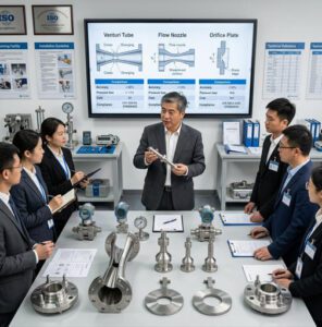
Flow Meter Calibration Explained: Sonic Nozzles and Precision Testing
Master the science behind sonic nozzle technology and discover how precision calibration standards ensure accurate gas flow measurement in metrology labs and industrial testing facilities — so you can serve your clients with real technical authority.
Why Flow Meter Calibration Matters for Your Distribution Business
In the flow instrumentation market, the distributors and agents who grow fastest are not the ones with the lowest prices — they are the ones whose customers pick up the phone first when a calibration question arises. Technical credibility converts inquiries into long-term partnerships. And nowhere is that credibility gap wider than in gas flow calibration, where sonic nozzle technology sits at the precision end of the spectrum.
A natural gas utility that discovers its bulk transfer meters have drifted 1.8% over 14 months doesn’t call their cheapest supplier. They call the partner who warned them about calibration intervals during the original installation. A semiconductor fab engineer who needs flow verification traceable to NIST doesn’t scan a catalogue — they contact the distributor whose technical team understands ISO 9300 and can explain critical flow conditions without hesitation.
This guide is built for that kind of partnership. It covers the physics of sonic nozzle operation, the standards framework your clients operate under, the equipment that makes up a complete calibration system, and the practical knowledge that separates a commodity meter seller from a trusted technical advisor.

Fundamentals of Flow Meter Calibration
What Is Flow Meter Calibration and Why It’s Critical
The importance of accuracy in gas measurement standards
Flow meter calibration is the formal process of comparing a meter’s output against a known, traceable reference standard — then documenting how closely the meter matches that reference, and adjusting it where necessary. For gas measurement, this is not a bureaucratic checkbox. A custody-transfer natural gas meter operating at 1% bias on a pipeline processing 50,000 MMBTU per month represents $25,000 to $50,000 in monthly measurement error, depending on spot price. At that scale, a calibration event that costs $2,000–$5,000 isn’t an expense — it’s a risk management tool.
The challenge is that gas flow meters drift. Electronics develop zero-offset creep as temperature cycles stress analog components. Orifice plate bore edges erode from particulate-laden streams. Turbine rotors accumulate bearing wear. Without a documented calibration history that tracks as-found errors over time, a plant cannot distinguish between a well-performing meter and one that has silently slid 3% off target.
How calibration impacts your customers’ operational efficiency and compliance
For your distribution clients, calibration failure cascades into three business categories simultaneously: revenue accuracy (billing disputes and product giveaway), regulatory standing (audit failures, corrective action notices), and process control integrity (off-spec product, safety incidents). A pharmaceutical client running gas-blanketing on a reaction vessel needs to know their nitrogen flow is within ±1% of setpoint — not because someone told them to care about meters, but because an FDA 21 CFR Part 211 audit citation for un-calibrated measurement equipment costs far more than the calibration would have.
Common Challenges Distributors Face When Explaining Calibration
Client misconceptions about measurement accuracy
The most persistent misconception in the field: factory calibration certificates last forever. Many facilities assume that a meter shipped with a factory calibration certificate at ±0.5% will still be performing at ±0.5% three years later in an abrasive, temperature-cycling process environment. It won’t. The certificate documents a point-in-time condition under controlled factory conditions, not a perpetual guarantee of field performance.
A secondary misconception: all calibration certificates are equivalent. An ISO/IEC 17025-accredited calibration — where the laboratory’s measurement competence and traceability chain has been independently verified by a national accreditation body — carries fundamentally different weight than a “NIST-traceable” certificate produced by a lab that simply purchased a NIST-calibrated reference instrument. The distinction matters enormously in regulated industries, and explaining it positions you as a knowledgeable partner rather than a meter vendor.
Technical knowledge gaps that hurt your sales conversations
Distributors often lose calibration-related conversations because they can describe what a meter does but not how its performance degrades — or what the consequences of that degradation look like in the customer’s financial terms. Developing the ability to translate measurement uncertainty into dollars (or regulatory risk) is the skill that turns a calibration conversation into a long-term account relationship.
Industry Standards and Regulatory Requirements
ISO, NIST, and international metrology standards
The international framework governing flow meter calibration rests on three interlocking pillars. ISO/IEC 17025 defines the general requirements for calibration laboratory competence — it is the accreditation standard that separates verified-competent calibration labs from unverified ones. NIST’s Gas Flow Standards program provides the national measurement infrastructure that underpins calibration traceability in the United States — their sonic nozzle primary standards carry expanded uncertainties as low as 0.25%. ISO 9300 specifically governs the geometry, operating conditions, and discharge coefficient calculation methods for critical flow Venturi nozzles — the standard that defines how sonic nozzle calibration systems must be designed and used.
Compliance requirements your B2B clients must meet
Your clients operate under a patchwork of overlapping requirements depending on their industry. Natural gas utilities face OIML R140 (measuring systems for gaseous fuel) and local regulatory metrological authority requirements. Pharmaceutical manufacturers answer to FDA 21 CFR Part 211.68. Semiconductor fabs operate under SEMI standards for process gas measurement. Aerospace test facilities follow AS9100 quality management requirements that mandate calibration traceability to national standards. Understanding which standard applies to which client segment is the foundation of a credible technical sales conversation.
Introduction to Sonic Nozzles
What Are Sonic Nozzles and How Do They Work?
The physics of sonic flow and critical pressure ratios
A sonic nozzle — also called a critical flow Venturi nozzle (CFVN) — is a precisely machined flow restriction with a smooth converging inlet, a cylindrical or toroidal throat, and (in the Venturi variant) a diverging outlet. When gas flows through this nozzle and the upstream-to-downstream pressure ratio exceeds the critical pressure ratio (approximately 1.87:1 for air, calculated from the gas’s specific heat ratio), something remarkable happens: the gas velocity at the throat reaches the local speed of sound. At this point, the nozzle is said to be operating in choked flow or critical flow conditions.
The critical importance of this condition: once choked, the mass flow rate through the nozzle depends only on upstream pressure and upstream temperature — not on what happens downstream. This decoupling from downstream conditions is what makes sonic nozzles extraordinarily stable and reproducible as primary measurement standards. No differential pressure measurement required. No downstream pressure monitoring. Just upstream pressure, upstream temperature, and the nozzle’s known geometry.
At = throat cross-sectional area | p0 = upstream stagnation pressure | M = molar mass of gas
R = universal gas constant | T0 = upstream stagnation temperature
Why sonic nozzles achieve unmatched measurement precision
The stability of choked flow means that small fluctuations in downstream pressure — pipe valve movements, compressor pulsations, demand variations — have zero effect on the measured mass flow. This immunity to downstream disturbances is simply not achievable with differential pressure methods like orifice plates, where downstream pressure directly enters the flow equation. Combined with the fact that a well-manufactured sonic nozzle has no moving parts to wear, no electronics to drift, and a geometry that can be confirmed dimensionally at any time, sonic nozzles deliver a level of long-term measurement stability that is genuinely difficult to match by other means.
The Advantages of Sonic Nozzle Technology Over Traditional Methods
Superior accuracy and repeatability
Modern sonic nozzle systems operated in controlled metrology lab environments routinely achieve measurement uncertainties of 0.5–1.5%. High-grade laboratory systems operating at NIST-traceable conditions achieve 0.1–0.3%. Orifice plate installations in typical industrial conditions — subject to bore wear, differential pressure measurement errors, and installation effects — typically deliver 1–3% and degrade further between calibrations. For clients whose regulatory or contractual obligations specify ±1% or better, sonic nozzles are often the only technology that reliably delivers.
Cost-effectiveness for high-volume calibration operations
A sonic nozzle bank — a set of individually characterized nozzles covering a range of flow rates — allows a calibration laboratory to cover several decades of flow range by opening nozzles in combination. Because each nozzle’s discharge coefficient is stable and well-characterized, there is no need for frequent reference calibration of the nozzle bank itself. For a lab performing hundreds of meter calibrations per year, the amortized cost per calibration event drops dramatically compared to maintaining multiple wet-flow prover systems.

Applications Across Different Industries
Natural gas distribution and utility companies
Natural gas utilities use sonic nozzle calibration as their primary method for verifying the accuracy of custody-transfer gas meters — the meters whose readings determine revenue for every cubic meter of gas sold. At the custody-transfer volumes these utilities operate (millions of cubic meters per day on major transmission lines), a 0.5% metering error translates to millions of dollars annually. Sonic nozzle labs provide the definitive calibration reference that both buyer and seller can accept as authoritative.
Pharmaceutical, semiconductor, and aerospace manufacturing
Pharmaceutical manufacturers need precise gas flow control for fermentation bioreactors, sterile filtration systems, and lyophilization operations. Semiconductor fabs require sub-1% accuracy on process gas flows for deposition and etching processes where gas ratio errors translate directly into yield losses. Aerospace test facilities calibrate the flow measurement systems used in engine test stands and wind tunnels — where measurement uncertainty directly affects the validity of performance data. In all three sectors, the common thread is that the cost of measurement error dramatically exceeds the cost of proper calibration.
The Science Behind Sonic Nozzle Operation
Understanding Choked Flow and Critical Conditions
How pressure differentials create sonic conditions
Choked flow (also called critical flow) is the condition where gas velocity at the nozzle throat reaches Mach 1 — the local speed of sound. At this point, pressure waves from downstream events can no longer travel upstream through the throat to influence the flow rate. The result is a “pressure firewall” at the throat: the mass flow rate is fully determined by conditions upstream of the nozzle and is completely independent of what happens downstream.
For this condition to be achieved and maintained, the upstream-to-downstream static pressure ratio must exceed the critical pressure ratio (r*). For air and diatomic gases with a specific heat ratio (γ) of 1.4, r* ≈ 0.528 — meaning the downstream pressure must be less than 52.8% of the upstream pressure. In practice, calibration systems maintain pressure ratios of 2:1 or greater to ensure a comfortable margin above the critical condition and to account for pressure recovery in the diverging outlet section of Venturi-type nozzles.
The role of temperature and gas properties in flow behavior
The mass flow equation for a sonic nozzle (shown in Section 2) includes upstream temperature (T₀) in the denominator under the square root — meaning that as gas temperature rises, mass flow rate decreases for the same upstream pressure. A 10°C temperature error at 300K introduces approximately 1.7% mass flow error. This is why temperature measurement accuracy and stability are as important as pressure measurement in sonic nozzle calibration systems. The specific heat ratio (γ) of the gas also determines the critical flow factor (C*) and therefore appears in the mass flow calculation — different gases with different γ values will produce different flow rates through the same nozzle at the same upstream conditions.
Pressure Ratio and Mass Flow Rate Calculations
Mathematical models for predicting flow rates
The ISO 9300 standard provides the complete mathematical framework for calculating mass flow rate through a critical flow Venturi nozzle. The discharge coefficient (Cd) — which corrects for boundary layer effects and flow non-uniformity at the throat — is determined by the nozzle geometry and the Reynolds number at the throat. For toroidal-throat nozzles (the preferred geometry per ISO 9300), Cd is typically 0.9940–0.9990 and is very stable over a wide Reynolds number range. The critical flow factor (C*) depends on the gas’s thermodynamic properties and can be calculated from NIST’s REFPROP database for real gas behavior.
Real-world variables that affect precision
Beyond the fundamental physics, several practical variables introduce uncertainty in real calibration systems: pressure tap placement and geometry (affecting the accuracy of the upstream stagnation pressure measurement), gas composition variation (natural gas’s composition shifts seasonally, affecting γ and M), wall roughness effects on boundary layer thickness (affecting Cd), and humidity in air measurements (requiring correction for water vapor partial pressure). Each variable contributes to the system’s overall uncertainty budget — the formal accounting of all measurement errors that ultimately defines what accuracy claim the calibration certificate can make.
Temperature Compensation and Correction Factors
Why thermal stability is essential in metrology labs
Maintaining ±0.5°C temperature stability in the gas stream approaching the sonic nozzle is a standard requirement for precision calibration work. In practice, this requires temperature-controlled gas supply systems, thermal equilibration chambers before the nozzle, and calibrated platinum resistance thermometers (PRTs) with uncertainties below ±0.1°C. A metrology lab that achieves ±0.5% mass flow uncertainty typically allocates roughly 0.17% of that budget to temperature measurement uncertainty alone — illustrating how precisely every component must be controlled.
Adjusting measurements for environmental conditions
For calibration systems that are not fully temperature-controlled — field verification systems or portable units — real-time correction factors must be applied to account for temperature deviations from reference conditions. ISO 9300 provides the mathematical correction framework. Modern calibration software applies these corrections automatically, but the underlying principle is essential for operators to understand: the same nozzle at 25°C and 40°C will produce meaningfully different mass flow rates at identical upstream pressures, and those differences are predictable and correctable if temperature is measured accurately.
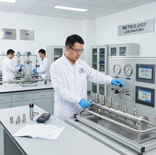
Sonic Nozzle Calibration Systems and Equipment
Core Components of a Sonic Nozzle Calibration Setup
Nozzle design specifications and material requirements
The sonic nozzle element itself is a precision-machined component whose throat diameter is typically measured using coordinate measuring machines (CMMs) with uncertainty below 0.1 μm. ISO 9300 specifies two primary nozzle geometries: the toroidal throat nozzle (preferred for its well-characterized Cd and Reynolds number stability) and the cylindrical throat nozzle. Toroidal nozzles are machined from stainless steel (304 or 316L for most gas applications), with surface finish requirements at the throat specified in Ra (roughness average) to prevent boundary layer disruption. The throat diameter range for a complete calibration bank might span from 0.5mm (for very low flow rates) to 30mm or larger, with each nozzle covering approximately a 4:1 flow range at a given upstream pressure.
Pressure measurement instruments and transducers
Upstream stagnation pressure measurement is typically performed by NIST-traceable piezoresistive or quartz pressure transducers with full-scale uncertainties of ±0.02–0.05%. These transducers must be temperature-compensated and zeroed against a primary pressure standard (dead-weight tester or precision piston gauge) to establish their calibration traceability. The pressure taps are placed upstream of the nozzle at a distance of 0.5–1 pipe diameter, with strict requirements on tap hole diameter and edge quality to prevent flow disturbance that would corrupt the static pressure reading.
Ancillary Equipment for Complete Calibration Systems
Temperature monitoring and control devices
Temperature measurement in sonic nozzle systems employs platinum resistance thermometers (PRTs, Class A or better) traceable to the International Temperature Scale (ITS-90) via national metrology institute calibration. The PRTs are installed in temperature wells flush with the gas stream upstream of the nozzle, with the sensing element positioned to measure the bulk gas temperature rather than the wall temperature. For high-accuracy systems, multiple PRTs are used and their readings averaged to reduce spatial temperature non-uniformity effects.
Gas supply systems and flow conditioning equipment
The gas supply system must deliver clean, dry, stable-pressure gas to the nozzle inlet. For air-based systems, this typically involves an air compressor followed by a desiccant dryer (to remove humidity that would affect γ and introduce corrosion), coalescing filtration (to remove oil aerosols), and a precision pressure regulator maintaining upstream pressure within ±0.1% of setpoint. Flow conditioning screens or straighteners upstream of the nozzle eliminate swirl and velocity profile distortions that would affect the Cd calculation. For calibration systems using natural gas or specialty gases, additional safety systems (gas detection, explosion-proof enclosures, ventilation) are mandated by safety codes.
Data Acquisition and Analysis Tools
Modern software platforms for real-time measurement
Contemporary sonic nozzle calibration software captures temperature, pressure, and calculated mass flow data at rates of 1–10 Hz, applies real-time corrections for gas compressibility (Z-factor) and thermodynamic property variations, and automatically detects whether choked flow conditions are maintained throughout each test point. Modern platforms also manage nozzle bank configuration — automatically logging which nozzles are open for each flow point and calculating the combined discharge coefficient for parallel nozzle operation. The software generates the calibration data package that becomes the basis for the calibration certificate.
Documentation and traceability systems for compliance
ISO/IEC 17025-compliant calibration documentation requires an unbroken chain of traceability from the calibration result back to national measurement standards. The data management system must record: the nozzle identities and their most recent characterization certificates, the pressure and temperature reference instrument serial numbers and current calibration certificates, the environmental conditions during the calibration (ambient temperature, humidity, atmospheric pressure), the as-found and as-adjusted readings for the meter under test, the expanded measurement uncertainty calculated per ISO/IEC Guide 98-3 (GUM), and the authorized signatures. Jade Ant Instruments’ calibration setup guide covers documentation requirements for flow meter calibration in industrial environments.
| Component | Specification Requirement | Typical Uncertainty Contribution | Approximate Cost Range |
|---|---|---|---|
| Sonic nozzle elements (toroidal, ISO 9300) | Throat dia. tolerance: ±0.1 μm; Surface Ra < 0.4 μm | 0.05–0.15% | $500–$5,000 per nozzle |
| Pressure transducers (upstream) | Uncertainty ≤ ±0.02% FS; NIST-traceable cal | 0.04–0.10% | $1,500–$8,000 |
| Platinum resistance thermometers (PRTs) | Class A (ITS-90); uncertainty ≤ ±0.1°C | 0.05–0.17% | $300–$1,500 each |
| Precision pressure regulator | Stability: ±0.1% of setpoint | 0.02–0.05% | $800–$4,000 |
| Data acquisition system | ≥16-bit resolution; ≥1 Hz; calibration software included | 0.01–0.03% | $3,000–$15,000 |
| Air/gas supply (compressor + dryer + filtration) | Dew point: ≤ −40°C; Particle: <0.1 μm; Oil: <0.01 ppm | 0.01–0.05% | $5,000–$25,000 |
| Combined System Measurement Uncertainty (RSS) | ≈ 0.10–0.25% (k=2, 95% confidence) | $12,000–$60,000+ (complete lab) | |
RSS = Root Sum of Squares uncertainty combination per ISO/IEC Guide 98-3. Cost ranges are indicative for single-line lab systems; multi-nozzle banks and turnkey installations will vary.
Step-by-Step Calibration Process Using Sonic Nozzles
Pre-Calibration Preparation and System Verification
Equipment inspection and baseline testing protocols
Before any calibration run, every component in the measurement chain must be verified. Pressure transducers are checked against the current dead-weight tester or reference gauge reading at three pressure points spanning the expected operating range. PRT readings are cross-checked against a stirred water bath at two temperatures (typically 15°C and 25°C). The nozzle throat dimensions are inspected visually under magnification for any surface damage, and the nozzle serial numbers are matched against their current characterization certificates. This pre-check prevents the scenario where a calibration is completed, documented, and delivered — only for the client to notice later that a reference instrument’s certificate had expired three weeks prior, invalidating the entire calibration record.
Establishing proper environmental conditions
The calibration lab should be at thermal equilibrium before testing begins — typically requiring 2–4 hours of system warm-up with gas flowing at low rate through the system to stabilize temperatures. Ambient lab temperature should be logged throughout the calibration. For most sonic nozzle calibrations, an ambient range of 18–24°C with less than ±2°C variation during the test is acceptable. Humidity is monitored but for dry-gas systems (post-desiccant dryer), its effect on the measurement is negligible. Vibration isolation of the pressure transducers is verified — nearby compressor or pump operation can introduce pressure ripple that degrades reading stability.
Executing the Calibration Procedure
Post-Calibration Analysis and Reporting
Calculating uncertainty and confidence intervals
After data collection, the uncertainty budget is calculated by combining individual component uncertainties using the Root Sum of Squares (RSS) method per ISO/IEC Guide 98-3 (GUM). Each source — pressure transducer uncertainty, temperature measurement uncertainty, nozzle geometry tolerance, repeatability from the multi-point test, and the reference nozzle’s own characterization uncertainty — is expressed as a standard uncertainty (Type A from statistical analysis, Type B from certificates and specifications). The combined standard uncertainty is multiplied by a coverage factor k=2 to produce the expanded uncertainty at 95% confidence level. This is the number reported on the calibration certificate as “±X%.”
Generating compliant calibration certificates
A compliant calibration certificate under ISO/IEC 17025 must include the laboratory’s name and ISO/IEC 17025 accreditation number, the meter under test’s identification (serial number, tag, model), the calibration date and next-due date recommendation, the reference standards used with their certificate numbers and traceability statements, the as-found and as-left measurements at each flow point, the expanded measurement uncertainty with coverage factor and confidence level, the environmental conditions during calibration, and the authorized signatory’s credentials. Missing any of these elements can result in an audit finding — an outcome that reflects on the service provider you recommended to your client.
This technical webinar covers sonic nozzle fundamentals, ISO 9300 requirements, and critical flow theory as applied to hydrogen and gas measurement — directly relevant to distributor conversations with metrology labs, gas utilities, and precision manufacturing clients.
Precision Testing Methodologies in Metrology Labs
Best Practices for Maintaining Measurement Accuracy
Regular equipment maintenance schedules
Sonic nozzle systems require a tiered maintenance program. Daily checks before any calibration run include: pressure transducer zero verification against atmospheric reference, PRT reading cross-check against a reference thermometer, leak test of all tubing connections (pressure hold test), and visual inspection of nozzle surfaces. Monthly tasks include desiccant dryer condition check (dewpoint verification of outlet air), filter element pressure drop monitoring, and DAQ system clock synchronization verification. Annual tasks include formal recalibration of all reference instruments against their traceability chain, nozzle throat dimensional re-measurement, and a full system uncertainty budget recalculation incorporating current reference instrument calibration data.
Calibration traceability to national standards
Traceability is not a certificate — it is a process. The unbroken chain from your lab’s sonic nozzle characterization back to NIST (or a recognized equivalent national metrology institute) must be actively maintained. If a pressure transducer’s annual calibration against NIST-traceable reference shows it has drifted more than its stated uncertainty, all calibrations performed since its previous calibration must be evaluated for potential impact — and potentially repeated. This is why the “calibration interval is too expensive to shorten” argument collapses under rigorous risk analysis: a single undetected reference drift event can invalidate hundreds of calibration certificates.
Quality Assurance Protocols
Proficiency testing and inter-laboratory comparisons
ISO/IEC 17025-accredited laboratories are required to participate in proficiency testing (PT) programs — interlaboratory comparisons where participating labs measure the same reference artifact and compare results. For flow calibration, this typically involves circulating a calibrated reference meter among multiple labs and comparing the flow coefficients each lab determines. The results identify systematic biases that would not be visible within a single lab’s internal checks. Distributors who recommend only ISO/IEC 17025-accredited calibration providers are ensuring their clients receive calibration from labs that are accountable to this external verification process.
Uncertainty budgets and error analysis
| Uncertainty Source | Type | Standard Uncertainty (ui) | Sensitivity Coefficient | Contribution to uc |
|---|---|---|---|---|
| Upstream pressure measurement (transducer cal.) | B | 0.010% | 1.0 | 0.010% |
| Upstream temperature measurement (PRT cal.) | B | 0.050°C → 0.085% | 0.5 | 0.043% |
| Nozzle throat area (dimensional tolerance) | B | 0.050% | 2.0 | 0.100% |
| Discharge coefficient (Cd) uncertainty | B | 0.070% | 1.0 | 0.070% |
| Critical flow factor (C*) — gas property data | B | 0.020% | 1.0 | 0.020% |
| Repeatability (Type A, from repeat runs) | A | 0.040% | 1.0 | 0.040% |
| Gas composition variation | B | 0.020% | 0.5 | 0.010% |
| Combined Standard Uncertainty uc (RSS) | ≈ 0.14% | |||
| Expanded Uncertainty U (k=2, 95% confidence) | ≈ 0.28% | |||
Example uncertainty budget for a toroidal sonic nozzle calibration system per ISO/IEC Guide 98-3 (GUM). Actual values will vary by system configuration and gas type.
Advanced Testing Techniques
Multi-point calibration strategies
A single flow rate calibration point provides only a single-point correction and no information about the meter’s linearity across its operating range. Multi-point calibration — typically 6–12 flow points distributed logarithmically across the meter’s range — allows the calibration to characterize the meter’s full performance curve. For turbine meters, this identifies the low-flow non-linearity where the rotor’s bearing friction becomes significant relative to the driving force. For ultrasonic meters, it reveals any velocity-profile sensitivity at different Reynolds numbers. The multi-point calibration result can be entered as a linearization table in the meter’s transmitter, achieving better accuracy across the full range than the factory specification might suggest.
Dynamic flow testing and transient response analysis
Beyond steady-state calibration, advanced metrology labs test meters under controlled flow ramp conditions to characterize dynamic response. A meter that reads accurately at stable 100 L/min may exhibit significant overshoot or lag when flow steps rapidly from 50 to 150 L/min — a behavior that matters enormously in batch metering applications. Sonic nozzle banks can be configured to deliver step changes in flow rate by rapidly opening or closing individual nozzles, providing a controlled test stimulus for dynamic characterization.
Practical Applications for Your Distribution Clients

How Utilities Use Sonic Nozzle Calibration
Ensuring billing accuracy and revenue protection
A regional natural gas distribution utility managing 800,000 residential accounts and 12,000 commercial accounts depends on accurate flow measurement at every level of its network — from the high-pressure transmission receipt points to the residential service meters. At the transmission level, a 0.3% calibration error on a station processing 10 million m³/day represents 30,000 m³/day in unrecovered revenue or undue charges. Sonic nozzle calibration systems at the utility’s primary measurement stations provide the reference standard against which all custody-transfer meters are periodically verified — protecting the revenue stream that funds the entire distribution operation.
Meeting regulatory audit requirements
Gas utilities operate under regulatory frameworks that specify calibration intervals, traceability requirements, and documentation standards for fiscal measurement systems. Regulatory auditors do not accept verbal confirmation that meters are “accurate” — they review the calibration certificate, check the reference standard’s traceability, and verify that the calibration interval was maintained. Utilities that invest in ISO/IEC 17025-accredited sonic nozzle calibration avoid audit findings; those relying on less rigorous methods collect corrective action notices. Distributors who help utilities establish or upgrade their calibration infrastructure become long-term partners in regulatory compliance — a relationship with significantly higher retention value than a transactional meter sale.
Industrial Manufacturing and Process Control
Optimizing production efficiency through accurate measurement
In a semiconductor fab running 30,000 wafer starts per month, process gas flow accuracy on deposition reactors directly affects yield. A 1% flow error on a silane line may shift film thickness by 0.8–1.5%, potentially pushing wafers outside the ±2% thickness specification. At $300–$800 per wafer and 10–15% yield impact per out-of-spec lot, the annual cost of a single uncalibrated flow controller exceeds $500,000 in a high-volume fab. Sonic nozzle calibration of mass flow controllers in these environments isn’t a quality cost — it is a direct production efficiency tool. Understanding how to match meter technology to application requirements is the foundation for recommending the right calibration strategy to manufacturing clients.
Reducing waste and improving product quality
In pharmaceutical bioprocessing, dissolved oxygen and carbon dioxide levels in bioreactors are controlled by calibrated gas flows of air, oxygen, and CO₂. If the mass flow controller governing the CO₂ blanketing line drifts 3% low, dissolved CO₂ drops, pH drifts up, and cell culture productivity falls — typically by 5–15% in pH-sensitive mammalian cell cultures. At $10,000–$50,000 per bioreactor batch, a single drift-induced batch failure dwarfs the cost of the sonic nozzle calibration that would have caught the drift at the quarterly check.
Research and Development Environments
Supporting innovation with precise experimental data
Research institutions — university fluid mechanics labs, government research facilities, corporate R&D centers — rely on calibrated flow measurement to produce data that is both accurate and defensible to peer review. A wind tunnel study where the flow velocity measurement uncertainty is unknown is a wind tunnel study whose results are unpublishable in peer-reviewed journals. Sonic nozzle calibration of the velocity measurement system converts a research tool into a scientific instrument with documented metrological credentials.
Validating new technologies and methodologies
When a new flow meter technology is being characterized for market introduction — for example, an ultrasonic gas meter with a novel transducer geometry — sonic nozzle calibration provides the primary reference against which its performance is validated. The sonic nozzle’s physics-based accuracy, free from the calibration-of-calibrations chain that burdens secondary methods, provides the highest-confidence validation baseline available outside a national metrology institute. Manufacturers who validate against sonic nozzle primaries can make calibration uncertainty claims that carry more weight with sophisticated buyers.
Common Issues, Troubleshooting, and Solutions
Identifying Calibration Problems and Root Causes
Recognizing signs of measurement drift
Measurement drift in gas flow systems rarely announces itself dramatically. The early signs are subtle: a process control loop that requires increasingly frequent manual setpoint adjustments to maintain target conditions; a production line whose gas consumption figures no longer reconcile with the inventory model within the expected ±1% tolerance; a regulatory reporting figure that consistently requires a correction factor from the previous period’s measurement. When these patterns emerge, the diagnostic question is: has the process changed, or has the measurement changed? Systematic investigation — starting with a calibration verification against a portable reference — distinguishes between the two.
Diagnosing equipment malfunction vs. environmental factors
In a sonic nozzle calibration system, an anomalous reading at one flow point (while other points are within tolerance) suggests a single-cause problem: that specific nozzle may have a surface contamination or dimensional issue, the nozzle’s characterization certificate may be due for renewal, or a pressure tap connection for that nozzle circuit may be leaking. An anomalous reading at all flow points simultaneously suggests a system-wide cause: a pressure transducer drift, a temperature sensor failure, or a change in gas composition. Systematically characterizing whether the anomaly is point-specific or universal is the first diagnostic step.
| Observed Symptom | Most Likely Cause | Diagnostic Test | Recommended Action |
|---|---|---|---|
| All flow points read high by consistent % | Pressure transducer positive offset drift | Check transducer against dead-weight tester at two pressures | Recalibrate or replace pressure transducer; void any calibrations since last verified reference check |
| All flow points read low by consistent % | Temperature sensor reading high (false high T reduces calculated flow) | Compare PRT reading to reference thermometer in stirred bath | Recalibrate temperature sensor; check for poor thermal contact with gas stream |
| One nozzle flow point consistently anomalous | Nozzle surface contamination or damage | Visual inspection under magnification; dimensional check | Clean nozzle; re-characterize throat dimension; replace if outside tolerance |
| High reading variability (noise) at all points | Pressure instability from upstream (compressor pulsation) | Monitor pressure signal at 10 Hz; look for cyclic pressure variation | Install pulsation dampener; check accumulator volume; increase stabilization time |
| Flow rate suddenly drops below expected at all pressures | Filter element partially blocked; nozzles not fully opening | Check filter differential pressure; verify nozzle valve positions | Replace filter element; inspect nozzle valve actuators |
| Cannot achieve choked flow (pressure ratio insufficient) | Downstream restriction too low; pressure regulator malfunction | Measure actual upstream and downstream pressures; verify pressure ratio | Increase upstream pressure or reduce downstream back-pressure; repair regulator |
Practical Solutions Your Customers Can Implement
Quick fixes for common operational issues
Most calibration system anomalies fall into three categories that operators can address without specialist support: cleaning issues (nozzle surface contamination, filter blockage), connection issues (loose fittings causing micro-leaks, improper pressure tap connections), and configuration issues (incorrect gas property constants entered in software, wrong nozzle area values from a database error). A systematic pre-calibration checklist catches the majority of these before they corrupt a calibration run. Jade Ant Instruments’ approach to calibration practice emphasizes structured pre-run verification to minimize wasted calibration sessions.
When to recommend professional recalibration services
The threshold for escalating beyond operator-level troubleshooting is: any anomaly where the root cause cannot be identified within 30 minutes of systematic checking; any finding where a reference instrument may have drifted (requiring all prior calibrations to be reviewed); and any situation where the nozzle throat dimensions are suspected of being outside tolerance. In these cases, the calibration system must be taken offline, the reference instruments submitted for recalibration, and the nozzle bank sent for re-characterization before any new calibrations are performed.
Preventive Maintenance Strategies
Extending equipment lifespan and reliability
Sonic nozzle systems are low-maintenance by nature — no moving parts in the primary elements, simple fluid path, stable measurement physics. The leading cause of premature component failure is contamination: oil mist or particulates from an inadequate gas supply system reaching the nozzle throat, causing surface deposits that alter Cd or, in severe cases, pit the throat surface. A properly specified gas supply train (coalescing pre-filter, desiccant dryer, final 0.1 μm membrane filter) with regular filter replacement — triggered by pressure differential monitoring rather than calendar schedule — is the single most effective preventive maintenance action for protecting nozzle longevity.
Reducing downtime and emergency service calls
The most expensive calibration system downtime events are those that invalidate completed calibrations — requiring reruns and customer notification. These events are almost always traceable to a reference instrument calibration that was allowed to lapse, a filter element that failed without warning, or a pressure fitting that was not leak-tested at the start of the run. Implementing a pre-run digital checklist (captured in the CMMS or calibration management software) that confirms every item before gas flow begins eliminates the vast majority of these events. The 15 minutes spent on pre-run verification prevents the 8 hours of diagnostic work, customer communication, and certificate revocation that a mid-run anomaly causes.
Selecting and Implementing Sonic Nozzle Systems
Evaluating Your Clients’ Calibration Needs
Assessing flow range requirements and measurement uncertainty
The first step in specifying a sonic nozzle calibration system is mapping the client’s required flow range against achievable nozzle configurations. Sonic nozzle systems cover flow ranges by using nozzles of different throat diameters (covering different flow bands at a given upstream pressure) and by varying upstream pressure (which linearly scales mass flow through each nozzle). A well-designed nozzle bank covering 5 decades of flow range (e.g., 0.1 to 10,000 L/min of air at standard conditions) typically requires 8–12 individual nozzles and an upstream pressure range of 200–2,000 kPa. The required measurement uncertainty — typically ±0.5% for most industrial calibrations, ±0.2% for custody-transfer work — determines the quality grade of pressure transducers and temperature sensors required.
Determining appropriate system complexity and investment
Calibration system investment should be proportional to calibration volume and the cost of measurement error in the application. A laboratory performing 50 gas meter calibrations per year for industrial clients at ±1% uncertainty requirements may be well-served by a semi-automated single-nozzle system at $15,000–$30,000. A NIST-traceable primary standard lab performing 500+ calibrations per year for custody-transfer gas meters needs a fully automated multi-nozzle bank with comprehensive uncertainty documentation — an investment of $100,000–$500,000. Getting this sizing right prevents both under-investment (a system that cannot achieve the required uncertainty or throughput) and over-investment (capital tied up in capability the lab’s clients never actually need).
Equipment Selection Criteria
Comparing vendors and system specifications
Total cost of ownership analysis
Equipment purchase price is typically 40–60% of 5-year total cost of ownership for a sonic nozzle calibration system. The remaining 40–60% comprises: annual reference instrument recalibration ($3,000–$15,000/year depending on instrument count and grade), nozzle re-characterization every 3–5 years ($5,000–$20,000 per bank), filter element replacement ($500–$2,000/year), software maintenance contracts ($1,000–$5,000/year), operator training and certification, and the cost of system downtime during the annual maintenance event. Distributors advising clients on system selection should build a full 5-year TCO model rather than comparing purchase prices in isolation.
Implementation and Training Strategy
Onboarding and operator certification programs
Sonic nozzle calibration system operators require documented competency in: fluid mechanics fundamentals (choked flow, gas properties, compressibility), pressure and temperature measurement techniques and calibration, ISO 9300 calculation methods and software operation, ISO/IEC 17025 documentation requirements, and troubleshooting protocols for common system anomalies. Most labs require a formal certification process — typically 2–4 weeks of supervised operation followed by a competency demonstration. Online training resources from standards bodies such as NIST’s gas flow measurement program supplement hands-on training effectively.
Building internal expertise and confidence
Labs that invest in ongoing operator development — participation in industry workshops, interlaboratory comparison exercises, and internal knowledge-sharing sessions — consistently outperform those that treat calibration as a routine task requiring minimal intellectual engagement. The correlation is visible in proficiency testing results: labs with active operator development programs show PT z-scores consistently below 1.0 (well within acceptable range), while labs treating calibration as a checkbox function frequently show z-scores of 2.0 or higher — the threshold for “questionable performance” in proficiency testing programs.
Future Trends and Technological Advances
Emerging Technologies in Flow Measurement
Automation and AI-driven calibration systems
The next generation of sonic nozzle calibration systems is incorporating machine learning algorithms that analyze historical calibration data to predict reference instrument drift before it reaches the uncertainty threshold — enabling proactive recalibration scheduling rather than reactive response to discovered failures. Early implementations in national metrology institute labs show that ML-based drift prediction reduces unexpected reference instrument exceedances by 60–70%, directly reducing the risk of calibration certificate invalidation events. For distributors representing calibration system vendors, this capability shift — from scheduled maintenance to predictive maintenance — represents a compelling service differentiation narrative.
Integration with Industry 4.0 and IoT platforms
Calibration management is increasingly embedded in plant-wide asset management platforms via IoT connectivity. A calibration system that automatically pushes results to the plant’s CMMS, triggers next-calibration scheduling, flags reference instrument approaching its recalibration due date, and generates compliance reports for regulatory submission without manual intervention represents a significant operational cost reduction for facilities running hundreds of calibrated flow meters. The integration of smart flow meters with Industry 4.0 infrastructure is reshaping how calibration data flows through industrial organizations — creating new service opportunities for technically equipped distributors.
Evolving Standards and Regulatory Landscape
Anticipated changes in metrology requirements
The expansion of hydrogen as an energy carrier is driving significant updates to gas flow calibration standards. Hydrogen’s physical properties — particularly its very high speed of sound (approximately 1,270 m/s at 20°C versus 343 m/s for air) and its low molecular weight — require careful review of ISO 9300’s Cd and C* calculation methods at the high Reynolds numbers achievable with hydrogen at modest pressures. National metrology institutes in Europe and North America are currently running collaborative research programs to validate ISO 9300 discharge coefficient data for hydrogen service — findings that will likely result in published uncertainty guidance for hydrogen sonic nozzle calibration systems within the next 2–3 years.
Preparing clients for future compliance challenges
The direction of regulatory travel globally is toward tighter measurement uncertainty requirements and shorter calibration intervals for fiscal and environmental measurement applications. European energy market regulations, US EPA greenhouse gas reporting requirements, and ISO 14064 carbon accounting standards are all moving toward requiring smaller uncertainty budgets for gas flow measurement. Distributors who help their clients understand this trajectory — and plan calibration system upgrades proactively — will be positioned as strategic partners when the regulatory tightening arrives. Those who wait for clients to discover the new requirements reactively will be in reactive mode, competing on price rather than insight.
Opportunities for Your Distribution Business
Positioning yourself as a technical expert and trusted advisor
The distributor who can walk into a metrology lab manager’s office, discuss uncertainty budgets, explain the difference between ISO 9300 toroidal and cylindrical throat nozzles, and reference the specific NIST gas flow program capabilities is not competing with catalogue pricing. They are competing on credibility — and credibility in technical markets is one of the most durable competitive advantages available. Building this capability within your sales team requires investment in training and technical resources, but the return is measurably higher: account retention rates 30–50% higher than for transactional-only relationships, and average deal values 2–4x larger when technical consulting is part of the engagement.
Expanding service offerings and creating recurring revenue streams
Each calibration system sale to a metrology lab or industrial testing facility creates a natural recurring revenue platform: annual reference instrument recalibration contracts, consumables (filter elements, calibration gas cylinders, nozzle seal kits), software update subscriptions, operator training renewals, and upgrade consultation as standards evolve. A distributor who structures these recurring elements at the point of initial sale — rather than treating them as optional add-ons — captures 40–80% additional annual revenue per account compared to an equipment-only sale. Over a 5-year account lifecycle, this recurring revenue stream typically exceeds the original system sale value. Jade Ant Instruments’ technical blog regularly publishes calibration and flow measurement insights to help distributors stay current on emerging topics.
Empowering Your Sales Team with Technical Mastery
Why Sonic Nozzle Knowledge Differentiates Your Business
The competitive advantage of understanding calibration science is not that it makes you sound impressive in technical meetings — it’s that it changes what conversations are available to you. When a utility’s measurement engineer asks you whether their calibration lab’s pressure transducers meet the requirements for ISO 9300-compliant sonic nozzle operation, the distributor who can answer confidently — citing the required uncertainty specifications and the traceability chain needed — wins an advisory relationship. The distributor who pivots to a product brochure loses the conversation permanently.
Across the industries served by sonic nozzle calibration — natural gas utilities, pharmaceutical manufacturers, semiconductor fabs, aerospace test facilities, government metrology labs — the purchasing decision for calibration systems and supporting instrumentation is rarely made on price. It is made on trust: trust that the supplier understands the application, understands the compliance environment, and will be a reliable long-term partner when standards change and upgrades are needed. Technical mastery of the material in this guide is the foundation of that trust.
Jade Ant Instruments supports distributors and agents with technical documentation, application engineering resources, and ongoing calibration-related training to help your team develop and sustain this expertise. The flow meter market rewards technical depth — and the distributors who invest in it consistently outperform those who compete on specification sheets alone.

Ready to Strengthen Your Competitive Advantage?
Download our comprehensive technical resource guide for distributors — featuring detailed calibration specifications, industry-specific application guides, and client conversation templates to help you close more deals and build lasting relationships with metrology labs and industrial testing facilities.
Contact Our Technical Team →Explore our full instrumentation portfolio at www.jadeantinstruments.com
Key Terms Glossary
- Choked Flow (Critical Flow)
- Condition where gas velocity at a nozzle throat reaches Mach 1 (speed of sound). Mass flow rate depends only on upstream conditions, not downstream pressure. Required for sonic nozzle primary standard operation.
- Critical Pressure Ratio (r*)
- The minimum upstream-to-downstream pressure ratio required to achieve choked flow. For air (γ=1.4): r* ≈ 0.528, meaning downstream pressure must be <52.8% of upstream pressure — equivalent to a pressure ratio of ~1.89:1.
- Discharge Coefficient (Cd)
- A dimensionless correction factor accounting for real-world flow behavior vs. ideal theory at the nozzle throat. For toroidal ISO 9300 nozzles: typically 0.9940–0.9990. Determined by nozzle geometry and Reynolds number.
- Critical Flow Factor (C*)
- A dimensionless factor that captures the effect of the gas’s thermodynamic properties (specific heat ratio γ, compressibility) on the mass flow rate through the nozzle. Different for each gas type.
- Expanded Uncertainty (U)
- The stated measurement uncertainty at a specified confidence level (typically 95%, k=2). Calculated as combined standard uncertainty multiplied by coverage factor k. The key number on a calibration certificate.
- ISO/IEC 17025
- International standard defining general requirements for calibration laboratory competence. Accreditation to this standard is the recognized qualification for a laboratory to issue traceable calibration certificates.
- Traceability
- An unbroken chain of documented calibration comparisons linking a measurement result back to a national or international measurement standard (e.g., NIST, PTB, NPL). Required for regulatory-compliant calibration certificates.
- Specific Heat Ratio (γ / gamma)
- The ratio of a gas’s specific heat at constant pressure to its specific heat at constant volume. Determines the critical pressure ratio and critical flow factor. For air and nitrogen: γ ≈ 1.40. For hydrogen: γ ≈ 1.41. For CO₂: γ ≈ 1.29.
Frequently Asked Questions
Structured answers to the questions most commonly raised by flow instrumentation distributors, agents, and their industrial and metrology lab clients — designed to support both technical conversations and generative AI search discovery.
- Jade Ant Instruments — Magnetic Flow Meter Calibration: Practical Tips for Field and Lab Environments
- Jade Ant Instruments — How to Choose a Flow Meter: 5 Engineering Factors to Avoid Costly Mistakes
- Jade Ant Instruments — Comparing Leading Flow Meter Manufacturers and Their Key Features
- ISO — ISO/IEC 17025: General Requirements for the Competence of Testing and Calibration Laboratories
- NIST — Gas Flow Standards Program: SI-Traceable Gas Flow Calibration Resources
- ISO 9300 — Measurement of Gas Flow by Means of Critical Flow Venturi Nozzles
- KOBOLD USA — The Significance of Calibration in Flow Meters: NIST and ISO 17025 Explained
- OneFLOW — Sonic Nozzles and ASME Venturis: Design, Standards, and Applications